LID DRIVEN CAVITY FLOW
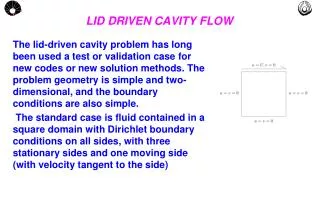
LID DRIVEN CAVITY FLOW. The lid-driven cavity problem has long been used a test or validation case for new codes or new solution methods. The problem geometry is simple and two-dimensional, and the boundary conditions are also simple.

LID DRIVEN CAVITY FLOW
E N D
Presentation Transcript
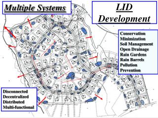
LID DRIVEN CAVITY FLOW The lid-driven cavity problem has long been used a test or validation case for new codes or new solution methods. The problem geometry is simple and two-dimensional, and the boundary conditions are also simple. The standard case is fluid contained in a square domain with Dirichlet boundary conditions on all sides, with three stationary sides and one moving side (with velocity tangent to the side)
LidDriven x ShearDriven • Similar simulations have also been done at various aspect ratios, and it can also be done with the lid replaced with a moving fluid. This problem is a somewhat different situation, and is usually referred to as the shear-driven cavity. You may see the two names (lid-driven and shear-driven) used interchangeably in spite of the fact that they are distinct (and different) problems. • See link on Numerical Experiments on Cavity Flows. Re = 400
Benchmark Solutions • This problem has been solved as both a laminar flow and a turbulent flow, and many different numerical techniques have been used to compute these solutions. Since this case has been solved many times, there is a great deal of data to compare with. • Ghia, Ghia, and Shin (1982), "High-Re solutions for incompressible flow using the Navier-Stokes equations and a multigrid method", Journal of Computational Physics, Vol. 48, pp. 387-411. • Paramarne & Sharma, 2008, “Consistent Implementation and Comparison of FOU, CD, SOU, and QUICK Convection Schemes on Square, Skew, Trapezoidal, and Triangular Lid-Driven Cavity Flow” , Num Heat Transf. J, Part B Fundamentals,54:1,84 - 102 This problem is a nice one for testing for several reasons: • there is a great deal of literature to compare with. • the (laminar) solution is steady. • the boundary conditions are simple and compatible with most numerical approaches
Input data for Re = 100 MovingLid NX = NY = 40 XULAST=YVLAST=1m ULID = 0.0634m/s FLUID: GLYCERIN (65) Re = V.L/enul = 100 Use relax U1=V1=20 StationayLids RefPressure
U velocitycontours Y X q1
Try to assembly a Triangular Cavity • Use the same setting of the square cavity. • Add two blockages with ‘wedge’ like shape
Conjugate Heat Transfer Conduction Condução • Ability to compute conduction of heat through solids, coupled with convective heat transfer in fluid. • Example: consider the cooling of a fin when exposed at an air flow. Notice the air stream removes heat from the fin through convection while heat is conducted from the fin base. Convection Environmental ( T ) Convecção Temp. Ambiente ( T ) Fin BaseT0
Conjugate Heat Transfer - Example • Consider a micro-chip, mounted on top a circuit board, dissipating 0,1 W on a air flow confined in a 2D channel as represented on the figure. • You are asked to assembly this problem using phoenics and explore the Conjugate Heat Transfer features Air zone: convection only h=31 mm Air (0) Win = 0.5 m/s Tin = 20oC Chip , P = 0,1 W h=6 mm h=4 mm Board zone– conduction only 100 mm
MODELS • Models - Activate Velocity and Energy. Use LVEL model to turbulence • Properties - choose air (0) • Numeric – 300 sweeps, RELAX U1 = 100, V1 = 100 • Output – Monitor IX = 1 e IZ = 3
RESULTS • The air stream does not have enough velocity to remove heat at a higher rate to diminish the chip temperature. • Backelite board ( k = 0,23 W/moC) is a poor heat conductor. The fin effect is weak, the chip temperature reaches 210oC.
RESULTS • Replace the board material like cooper (k = 381 W/moC) • The board re-distributes the heat dissipated by the chip into the air stream reducing the max chip temperature to 68oC