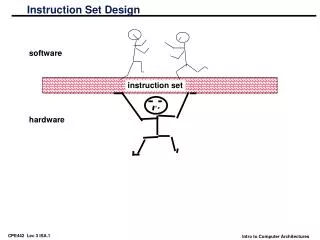
INSTRUCTION SET DESIGN
INSTRUCTION SET DESIGN. Jehan-François Pâris jparis@uh.edu. Chapter Organization. General Overview Objectives Realizations The MIPS instruction set. Importance. The instruction set of a processor is its interface with the outside world Defined by the hardware


INSTRUCTION SET DESIGN
E N D
Presentation Transcript
INSTRUCTION SET DESIGN Jehan-François Pâris jparis@uh.edu
Chapter Organization • General Overview • Objectives • Realizations • The MIPS instruction set
Importance • The instruction set of a processor is its interface with the outside world • Defined by the hardware • Used by assemblers, compilers and interpreters • Remained very visible to the users up to the 80’s • Earlier PC programs were written in assembler
Common features • A machine instruction normally consists of • An operation code • One, two or three operand addresses • Various flags • Some operands can be immediate • Address field contains the value of the operand instead of its address
Common features • One or more operands can be in high-speed registers • Dedicated registers: • Very old solution • Register address can be specified in the opcode • General purpose registers
Common features • Memory operand addresses are represented in a compact form • Base + displacement: • The address is specified by the contents of a base register plus a displacement • Saves space because displacement is generally small
Objectives • IS should be • Expressive: • Powerful instructions • Designed for speed: • Should be able to run fast and allow extensive prefetching • Compact: • Faster fetches from disk and from main memory
Objectives • User friendly: • Very important when people were expected to program is assembler • Manufacturers loved that because • Instruction sets were mostly proprietary:IBM 360/370 was the exception • Programs could not be ported to a different architecture
The story of Gene Amdahl • Raised on a farm without electricity until he went to high school • PhD from U Wisconsin-Madison • Became one of the top architects of the IBM/360 series • Had his next design rejected by IBM • Started his own company (Amdahl ) building big mainframes and selling them at a much lower cost than comparable IBM machines
How could they do that? (II) • Amdahl could undersell IBM by focusing on larger "mainframes" • Andahl's computers were air-cooled while IBM's water-cooled • "[D]ecreased installation costs by $50,000 to $250,000." • http://www.fundinguniverse.com/company-histories/amdahl-corporation-history/
How could they do that? (I) • IBM 360 series was first series of computers with • Very different capacities • Same instruction set • IBM pricing policy was keeping computer prices proportional to their capacity • Did not reflect proportionally lower manufacturing cost of high-end machines
The end of the story • Left Amdahl in 1979 to pursue unsuccessfully several ventures • Amdahl Computers is now part of Fujitsu and focuses on services
Inherent conflicts • Expressiveness vs. Speed • CISC instructions were powerful but microcoded • Compactness vs. Speed • Many instruction sets had instructions of different length • Cannot know start of next instruction before decoding the opcode of current one
What is microcode? • Some machine language below the instruction set • Invisible to the programmer/compiler • Each instruction corresponded to one or more microinstructions • Some architectures allowed the user to program new instructions or a whole new instruction set
The 360 architecture (I) • Developed in the 60’s but kept almost unchanged for 30+ years • Thirty-two bit words and 8-bit bytes • Memory was byte-addressable • Had 24-bit addresses restricting main memory size to 16 MB (enormous at that time!) • Later extended to 32 then 64 bits
The 360 architecture (II) • Instruction set included • 32-bit operations for scientific and engineering computing (FORTRAN) • Byte-oriented operations for character processing and decimal arithmetic then judged essential for business applications • Name of series referred to wide range of applications that could run on the machine
Opcode R1 R2 IBM 360 instruction set (I) • Had multiple instructions formats all with • Mostly 8-bit opcodes • 16 general purpose registers • RR (register to register) • 16 bits
Opcode R1 X2 B2 D2 IBM 360 instruction set (II) • RX (register to/from indexed storage) • 32 bits • Address of memory operand was:contents of base and index registers plus12-bit displacement D
Opcode I B D IBM 360 instruction set (III) • SI ( storage and immediate) • 32 bits • Has an 8-bit wide immediate field I • Address of memory operand was:contents of base register B plus12-bit displacement D
Opcode L B1 B2 D1 D2 IBM 360 instruction set (IV) • SS ( storage to storage) • 48 bits • Two memory operands • First addresses offields of length L
Opcode B D IBM 360 instruction set (V) • S ( storage ) • 32 bits with a 16-bit opcode • Mostly for privileged instructions
Discussion (I) • Flexible and compact • Multiple instruction sizes • Must decode current instruction to know start of the next one • Regular design • Many operations can be RR, RS, RX, SI and SS (character manipulation and decimal arithmetic)
Discussion (II) • RX format: • Memory address is indexed by base register and index register • a[i] can be decomposed into • Current base register • Offset of a[0] relative to base register • Index i multiplied by size of array element in index register
Discussion (III) • Why such a complex addressing format? • Index register was used to access arrays • Base register allowed for a much shorter address field • 4 bits for base register + 12 bits for displacement vs • 24 bits for a full address
MIPS (I) • Originally stood for Microprocessor without Interlocked Pipeline Stages • First RISC microprocessor • Development started in 1981 under John Hennessy at Stanford University • Started a company:MIPS Computer Systems, Inc.
MIPS (II) • Owned by SGI from 1992 to 1998 • Until SGI switched to the Intel Itanium architecture • Used by used by DEC, NEC, Pyramid Technology, Siemens Nixdorf, Tandem and others during the late 80s and 90s • Until Intel Pentium took over • Now primarily used in embedded systems
Overview • Two versions • MIPS32 with 32-bit addresses (discussed here) • MIPS64 with 64-bit addresses • Both MIPS architectures have • Thirty-two registers (32 bits on MIPS 32) • A byte-addressable memory • Byte, half-word and word-oriented operations
Bit ordering • All examples assume that byte-ordering islittle-endian: • Bits are numbered from right to left 0 31
Number representation (I) • MIPS uses two’s complement representation for negative numbers: • 00….0 represents 0 • 00….1 represents 1 • 01….1 represents 2n–1 – 1 • 10….0 represents – 2n–1 • 11….1 represents – 1
Two-complement representation • Assume n-bit integers • All positive integers have first bit equal to zero • All negative integers have first bit equal to one • To negate an integer, we compute its complement to 2n in unsigned arithmetic
Example • Assume n = 4 • 0000, 0001, 0010, 0011, 0100, 0101, 0110 and 0111 represent integers 0 to 7 • To find the representation of -3, we do • 16 -3 = 13, that is, 1101 • More generally 1000, 1001, 1010, 1011, 1100, 1101, 1110, 1111 represent negative integers -8 to -1
all zeroes 100……101 all ones 100……101 Number representation (II) • Can create problems when we fetch a byte or half-word into a 32 bit register • If we fetch the 16-bit half-word • we have two possible outcomes 100……101 (unsigned) (signed)
MIPS instruction set • Designed for speed and prefetching ease • All instructions are 32-bit long • Five instruction formats • Three basic formats • R, I and J • Two floating point formats • FR and FJ
rd rt shamt rs funct opcode The R format • Six-bit opcode • R instructions have three operands • Five bits per register 32 registers • Shamt specifies a shift amount (5 bits) • Funct selects the specific variant of operation defined in opcode (6 bits) • Many R instructions have an all-zero opcode
Register naming conventions • $s0, $s1, …, $s7 for saved registers • Saved when we do a procedure call • $t0, …, $t9 for temporary registers • Not saved when you do a procedure call • $0 is the zero register: • Always contains zeroes • Other conventions are used for registers used in procedures calls
R format instructions (I) • Arithmetic instructions • add $sa, $sb, $sc # a = b + c; • sub $sd, $se, $sf # d = e – f; • Logical instructions • and $sa, $sb, $sc # a = b & c; • or $sd, $se, $sf # d = e | f; • nor $sg, $sh, $si # g = ~(h | i); • xor $sj, $sk, $sl # j = (k&~l)|(~k&l)
Notes • MIPS logical instructions are bitwise operations • Implement bitwise & and I operations of C • MIPS has no negation instructions • Use NOR and specify register $0 as one of the two input registers • $0 is hard-wired to contain zero • nor $sk, $sl, $0 # k = ~l;
R format instructions (II) • More arithmetic instructions • addu $s1, $s2, $s3 • subu $s1, $s2, $s3 • Unsigned versions of add and sub • Multiply and divide instructions will be covered later
R format instructions (III) • Shift instructions • sll $s1, $s0, n • slr $s1, $s0, n • Shift contents of source register $s0 by n bits to the left (sll) or to the right (slr) • Fill the emptied bits with zero • Store results in destination register $s1
Notes (II) • A right shift followed by a logical and can be used to extract some specific bits • If we are interested in bits 14-15 of register $s0 • We set up a register $s2 containing 011two • We do • slr $t0, $s0, 14 # use temporary register $t0 • and $s1, $t0, $s2 # answer is in $s1
Notes (III) • Want to extract bits XY in positions 14 and 15 • slr $t0, $s0,15 • and $s1, $t0, $s2 # $s2 contains mask 011 ?????????????????xy?????????? 0000000000??????????????????xy 000000000000000000000000000xy
R format instructions (IV) • Register comparison instructions • slt $t0, $s3, $s4 • sltu $t0, $s3, $s4 • Sets register $t0 to 1 if $s3 < $s4and to 0 otherwise • slt does a signed comparison • sltu does an unsigned comparison
R format instructions (IV) for big jumps • Jump instructions • jr $s0 • Jump to address contained in register $s0 • Since $s0 can contain a 32-bit address, the jump can go anywhere • jalr $s0, $s1 • Jump to address contained in register $s0 and save address of next instruction in register $s1 (defaults to register 31)
rt rs opcode The I format constant/address • Last field can be • a 16-bit displacement:Address of memory operand is the sum of the contents of register rt and this displacement • a 16-bit constant:Register rt can then specify a second register operand
Discussion • I format contains instructions involving • One register and a memory location • Two registers and an immediate value • Two registers and a jump address relative to the current value of the program counter (PC) • MIPS instruction set uses the same format for three very different instruction styles • Simplifies decoding hardware