Download
1 / 26
270 likes | 683 Vues
Analog Filters: Basics of OP AMP-RC Circuits. Stefano Gregori The University of Texas at Dallas. Introduction. So far we have considered the theory and basic methods of realizing filters that use passive elements (inductors and capacitors)

E N D
Analog Filters:Basics of OP AMP-RC Circuits Stefano Gregori The University of Texas at Dallas
Introduction • So far we have considered the theory and basic methods of realizing filters that use passive elements (inductors and capacitors) • Another type of filters, the active filters, are in very common use • They were originally motivated by the desire to realize inductorless filters, because of the three passive RLC elements the inductor is the most non-ideal one (especially for low-frequency applications of filters in which inductors are too costly or bulky) • When low-cost, low-voltage solid-state devices became available, active filters became applicable over a much wider frequency range and competitive with passive ones • Now both types of filters have their appropriate applications Basics of OP AMP-RC Circuits
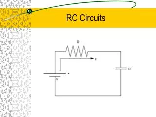
Active-RC filters In this lesson we concentrate on active-RC filters. They make use of active devices as well as RC components. Active filters • are usually designed without regard to the load or source impedance; the terminating impedance may not affect the performance of the filter • it is possible to interconnect simple standard blocks to form complicated filters • are noisy, have limited dynamic ranges and are prone to instability • can be fabricated by integrated circuits Passive filters • the terminating impedance is an integral part of the filter: this is a restriction on the synthesis procedure and reduces the number of possible circuits • are less sensitive to element value variations • are generally produced in discrete or hybrid form Basics of OP AMP-RC Circuits
Operational Amplifier symbol equivalent circuit In an ideal op-amp we assume: • input resistance Ri approaches infinity, thus i1 = 0 • output resistance Ro approaches zero • amplifier gain A approaches infinity Basics of OP AMP-RC Circuits
Inverting voltage amplifier Example: vin(t) given R1 = 1 kΩ R2 = 2 kΩ V0 = 1 V f = 1 MHz vout(t) we have Basics of OP AMP-RC Circuits
Weighted summer Basics of OP AMP-RC Circuits
Noninverting voltage amplifier Example: vin(t) given R1 = 1 kΩ R2 = 1 kΩ V0 = 1 V f = 1 MHz vout(t) we have Basics of OP AMP-RC Circuits
Buffer amplifier Basics of OP AMP-RC Circuits
Inverting or Miller integrator R = 1 kΩ C = 1 nF V0 = 1 V f = 1 MHz Example: vin(t) given vout(t) we have Basics of OP AMP-RC Circuits
Inverting differentiator (1) Example: given R = 1 kΩ C = 100 pF V0 = 1 V f = 1 MHz vin(t) vout(t) we have Basics of OP AMP-RC Circuits
Inverting differentiator (2) R = 22 kΩ C = 47 pF vin(t) is a triangular waveform with: - vin max 2 V - vin min 0 V - frequency 500 kHz vin(t) vout(t) is a square waveform with: - vout max 2,068 V - vout min -2,068 V - frequency 500 kHz vout(t) Basics of OP AMP-RC Circuits
Inverting lossy integrator Basics of OP AMP-RC Circuits
Inverting weighted summing integrator Basics of OP AMP-RC Circuits
Subtractor Basics of OP AMP-RC Circuits
Integrator and differentiator frequency behavior integrator differentiator integrator differentiator vin(t) is a sinewave with frequency f. Figure shows how circuit gain AV changes with the frequency f AV is the ratio between the amplitude of the output sinewave vout(t) and the amplitude of the input sinewave vin(t) R = 1 kΩ C = 1 nF Basics of OP AMP-RC Circuits
Low-pass and high-pass circuits low-pass circuit frequency behavior low-pass high-pass high-pass circuit R = 1 kΩ C = 1 nF Basics of OP AMP-RC Circuits
Inverting first-order section inverting lossing integrator Basics of OP AMP-RC Circuits
Noninverting first-order section noninverting lossing integrator Basics of OP AMP-RC Circuits
Finite-gain single op-amp configuration Many second-order or biquadratic filter circuits use a combination of a grounded RC threeport and an op-amp Basics of OP AMP-RC Circuits
Infinite-gain single op-amp configuration Basics of OP AMP-RC Circuits
Gain reduction To reduce the gain to α times its original value (α < 1) we make and solving for Z1 and Z2, we get and Basics of OP AMP-RC Circuits
Gain enhancement A simple scheme is to increase the amplifier gain and decrease the feedback of the same amount Basics of OP AMP-RC Circuits
RC-CR transformation (1) is applicable to a network N that contains resistors, capacitors, and dimensionless controlled sources conductance of Gi [S] → capacitance of Gi [F] capacitance of Cj [F] → conductance of Cj[S] • the corresponding network functions with the dimension of the impedance must satisfy • the corresponding network functions with the dimension of the admittance must satisfy • the corresponding network functions that are dimensionless must satisfy Basics of OP AMP-RC Circuits
RC-CR transformation (2) N N’ Basics of OP AMP-RC Circuits
Sallen-Key filters lowpass filter frequency behavior lowpass highpass bandpass highpass filter R = 1 kΩ C = 1 nF Basics of OP AMP-RC Circuits
Types of biquadratic filters lowpass highpass bandpass bandreject allpass Basics of OP AMP-RC Circuits