Download
1 / 32
430 likes | 1.03k Vues
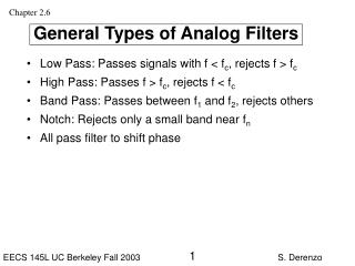
Analog Filters: Biquad Circuits. Franco Maloberti. Introduction. Active filters which realize the biquadratic transfer function are important building blocks (biquad). w p. w 0. p. Introduction. Biquads can build high-order filters. Poles and zeros are Real or complex conjugate.

E N D
Analog Filters: Biquad Circuits Franco Maloberti
Introduction • Active filters which realize the biquadratic transfer function are important building blocks (biquad) wp w0 p Analog Filters: Biquad Circuits
Introduction • Biquads can build high-order filters Poles and zeros are Real or complex conjugate s or 1/s B1 B2 B3 Problem: how to properly pair poles and zeros Analog Filters: Sensitivity
Single Amplifier Configurations - RC A + - RC - A RC A + + R R(k-1) R(k-1) R Enhanced positive or negative feedback Analog Filters: Sensitivity
Sallen-Key Biquad R1 R2 E2 E1 C2 C1 Only real poles (or zeros) E1 E2 C1 C2 The feedback permits us to achieve complex poles Analog Filters: Sensitivity
Sallen-Key Biquad (ii) C1 R1 R2 E2 E1 E4 E3 C2 Rb Ra Analog Filters: Sensitivity
Sallen-Key Biquad (ii) • Five design elements, two properties (G is not important) Case 1: C1=C2; R1=R2=R R=1/ 0m =3-1/Q Case 2: C1=C2; Ra=Rb R1=Q/ 0 R2=1/Q 0 Case 3: R1=R2; m=1 C1=2Q/ 0 C2=1/2Q 0 Case 4: C1=31/2Q C2; m=4/3 R1=1/Q0 R2=1/31/20 Analog Filters: Sensitivity
Sallen-Key Biquad (iii) • Sensitivities Analog Filters: Sensitivity
Sallen-Key High- and Band-pass R1 R2 E2 E1 LP C2 C1 C1 C2 E2 E1 C2 C1 R1 R2 HP R2 C1 E2 E1 R1 BP C2 Analog Filters: Sensitivity
Generic Sallen-Key Analog Filters: Sensitivity
Sallen-Key: finite op-amp gain • The inverting and non-inverting terminals are not virtually shorted C1 R1 R2 E2 E1 E4 E3 C2 Rb Ra Analog Filters: Sensitivity
Sallen-Key in IC C1 R1 R2 E2 E1 E4 E3 C2 Rb Ra C1 R1 R2 E2 E1 E4 E3 C2 Analog Filters: Sensitivity
LP Sallen-Key with real op-amp Analog Filters: Sensitivity
LP Sallen-Key with real op-amp (ii) The transfer function has two zeros and three poles. If k = Rgm >> 1 the zeros are practically complex conjugates and are located at The extra-pole is real and is located around the GBW of the op-amp. Analog Filters: Sensitivity
LP Sallen-Key with real op-amp (iii) Possible responses Analog Filters: Sensitivity
Sallen-Key IC Implementations Analog Filters: Sensitivity
Band-reject Biquad • A band-reject response requires zeros on the immaginary axis • It can be obtained with the generic SK implementation • Another option is to use a twin-T network Analog Filters: Sensitivity
Band-reject Biquad (ii) • Using complementary values Analog Filters: Sensitivity
Use of Feed-forward Assume High-pass Band-pass Analog Filters: Sensitivity
Infinite-Gain Feedback Biquad • Sallen-Key architectures require input common mode range. • Input parasitic capacitance of the op-amp can affect the filter response • Keep the inputs of the op-amp at ground or virtual ground Analog Filters: Sensitivity
Infinite-Gain Multi-Feedback Biquad • A conventional op-amp amplifier is not able to realize complex-conjugate poles • Two or more feedback connections achieve the result Analog Filters: Sensitivity
Low-Pass MFB Analog Filters: Sensitivity
Design and Sensitivity • Five elements and three equations • “Arbitrarily choose two of them and determine the remaining three parameters • Assess the “quality of design” • Sensitivity on relevant design element • Spread of components • Cost of the implementation • Linearity of components Analog Filters: Sensitivity
High-pass and Band-pass Analog Filters: Sensitivity
Two-Integrators Biquad • Use of state-variable method • Derive the block diagram • Translate the block diagram into an active implementation • Addition or subtraction • Integration • Dumped integration (integration plus addition) Analog Filters: Sensitivity
Basic Blocks Analog Filters: Sensitivity
State Variables The state variable are relevant voltages of the network E1 E2 G a0 E1 E2 E6 E5 E5 E6 E4 Analog Filters: Sensitivity
State Variables (ii) E3 E4 E3 E6 Analog Filters: Sensitivity
State Variables (iii) E4 E3 E6 E3 Analog Filters: Sensitivity
State Variables (iv) a0 -a1 + E2 a2 Analog Filters: Sensitivity
Implementations • Kervin-Huelsman-Newcomb • Tow-Thomson • Fleischer-Tow • …. • Fleischer-Laker Analog Filters: Sensitivity
Implementations (ii) Analog Filters: Sensitivity