SlideServe
Menu
Préférences
© SlideServe · v2026

Multi-Channel Electronics

alexia avatar
20 diapositives · 377 Views · Aug 31, 2014

This document details the design and functionality of the Multi-Channel Electronics (MCE) for SCUBA2 and SPIDER projects. It includes specifications for the readout cards (RC), bias cards (BC), address card (AC), and clock card (CC), along with their capabilities for processing 14-bit ADC signals. It discusses features for cooling systems, power supply options, and additional enhancements for bias modulation schemes. Emphasis is placed on the latest modifications for ensuring stable functionality and synchronization across various components while addressing SEU tolerance and FPGA advancements.
Multi-Channel Electronics - slide 1
01 / 20Multi-Channel Electronics
1 / 17

Télécharger la présentation

Multi-Channel Electronics
Une image / un lien ci-dessous est fourni (tel quel) pour télécharger la présentation

Politique de téléchargement : le contenu du site vous est fourni TEL QUEL pour votre information et votre usage personnel ; il ne peut être vendu, concédé sous licence ni partagé sur d’autres sites sans l’accord de son auteur.Le contenu vous est fourni TEL QUEL, pour votre information et votre usage personnel uniquement. Téléchargez la présentation en cliquant sur ce lien. Lors du téléchargement, si vous ne parvenez pas à télécharger une présentation, l’éditeur a peut-être supprimé le fichier de son serveur.Pendant le téléchargement, si vous ne parvenez pas à obtenir une présentation, le fichier a peut-être été supprimé par l’éditeur.

F I N

Plus de contenu associé

Transcription de la présentation
  1. Multi-Channel Electronics

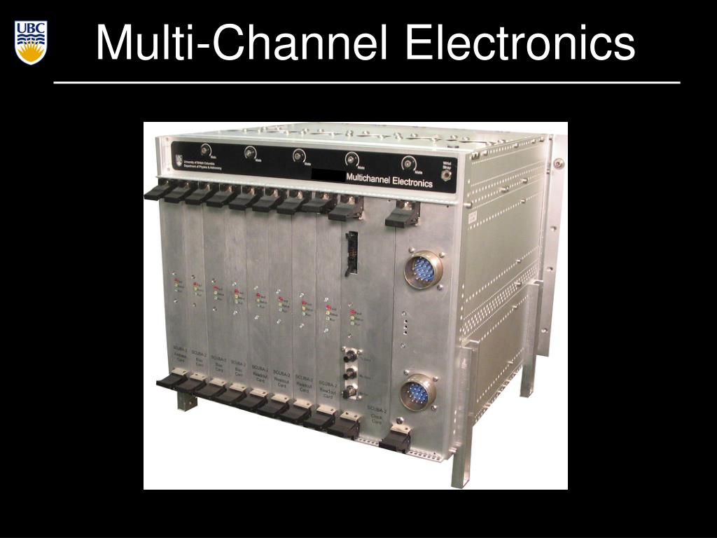
  2. SCUBA2 MCE • 4 readout cards (RC) • each reads 8 output columns through 14-bit 50MHz ADCs • 1 address card (AC)= SQ1_bias • addresses the [41] rows at add≤ 850kHz, set by L/R • frame≤add /41≈ 20kHz • 1 clock card (CC) • master card: interprets commands and synchronizes all the cards. Drives fibre to PC. • 3 bias cards (BC) • BC 1: Squid Series Array Feedback (x32) + TES bias(x1) • BC 2: Squid 2 feedback (x32) • BC 3: SQ2 bias(x32) + TES heaters(x1)

  3. SPIDER MCE • SPIDER (as well as SPUD and BICEPII) have up to 33 rows and 16 columns for each array • Repackaged MCE: • 2 RC’s • Reorganized BC’s duties • Additional features: • More DET_BIAS (already in place) • SQ2_fb fast switching (to achieve a better lock and to remove summing coil pickup switching off all SQ1_bias and adjusting SQ2_fb. However with fixed values. Or we could effectively connect the dark SQ sq1_fb with the sq2_fb)

  4. Cards in SPIDER MCE • 3 BC’s • BC1  0/16 SSA_fb, 0/16 SQ2_BIAS, DET_BIAS_ORG • BC2  0/16 (possibly fast switching) SQ2_FB • BC3  0/16 DET_BIAS • In the current configuration slow SQ2_FB and 16 DET_BIAS slightly different from DET_BIAS_ORG • 2 RC’s • RC1  0/7 SQ1_FB, 0/7 SSA_BIAS • RC2  8/15 SQ1_FB, 8/15 SSA_BIAS • 1 AC, 1 CC

  5. Subrack in SPIDER MCE T Felton design

  6. Backplane in SPIDER MCE SQ1_fb: it was 450A, now 150 A because of the increase in the mutual inductance of MUX06. Is it fine? DET_BIAS: the maximum we can achieve now is 4mA. It can be increased. Should it?

  7. PSU in SPIDER MCE • Power supply: • We currently use an ACDCU with a switching power supply • For SPIDER: • we may use batteries • 119W for SCUBA2. For SPIDER: 16 columns  73W (23W each RC)

  8. Cooling SPIDER MCE to the gondola frame, used as heatsink • Cooling: • We currently • use fans and • filtered air with positive pressure • SPIDER MCE will be radiatively cooled using circulating • fluid with a pump T Felton design

  9. SEU in SPIDER MCE • Cosmic rays on FPGA and SEU tolerance: 1 per month at JCMT ~1 SEU / board / LDB flight. We are already in contact with the TRIUMF particle accelerator for realistic neutron fluency test (in fact, test flight would not reveal the real effect). • Altera Stratix III FPGA’s offer additional on chip monitoring and testing features wrt Stratix I. We would not use it for the test flight. Maybe for SPIDER. • PC’s in pressure vessel (HD). Two with crosscomunication. • The syncbox could be there as well.

  10. Schedule for SPIDER MCE • For the new repackaged MCE with no cards redesign: • Finalize the design  1-2 weeks • Backplane  6-8 weeks • Chassis  our machine shop, 6 weeks • New FPGA? Probably not for the test flight. Maybe for SPIDER • Cooling system  4-5 weeks • New filter box and flex (rigid-flex, 1 connector less, and no ground plane)  6-8 weeks • Test  6-8 weeks • SEU test  ? • New boards  new year

  11. Modulation schemes • TES bias • SQ1 bias • SQ1 fb (switching) • SQ1 fb (ramping)

  12. TES bias • The TES bias could be square (or sine) wave modulated at ~1kHz. We have the firmware for s.w. that can run as fast as half the framerate • However, if the bias crosses zero for more than few hundreds s, than the TES’ may not recover Superconducting branch Normal branch Superconducting transition Acquired on the ACT CCam camera

  13. TES bias • In any TES bias modulation scheme we need a firmware that has to run two separate servo loops. Synchronization is needed. Major firmware change for the read-out and the demodulation. • It can be tested in software since we can already acquire fast data at 2.2kHz (33 rows, 32GB/h), 26kHz (1row). We’d need bolometers to do tests. Acquired on the ACT MBAC camera

  14. TES bias • In any TES bias modulation scheme we need a firmware that has to run two separate servo loops. Synchronization is needed. Major firmware change for the read-out and the demodulation. • It can be tested in software since we can already acquire fast data at 2.2kHz (33 rows, 32GB/h), 26kHz (1row). We’d need bolometers to do tests.

  15. SQ1 bias modulation • We visit the SQ1 at up to 20kHz with RS on bias. We could select 2 different on bias’ and switch at sub-harmonics of 20kHz. • The firmware demodulation (i.e. remove off from on) would be straightforward since it would be a modification of the coadding we already implement. Acquired on the ACT CCam camera

  16. SQ1 bias modulation • We visit the SQ1 at up to 20kHz with RS on bias. We could select 2 different on bias’ and switch at sub-harmonics of 20kHz. • We could invert the polarity of the SQ1_bias (although now it is not bipolar) and keep the same inverted polarity lock point. Acquired on the ACT CCam camera

  17. SQ1 fb modulation (switch) • The SQ1_fb could be switched so that the PID feedback loop works in opposite SQ1 slope • A firmware should be created that enables opposite locking. That could be done with I-term=I·(-1)#frames except that it would take time • However it should require a fine tuning and • … Acquired on the ACT CCam camera

  18. SQ1 fb modulation (switch) • The SQ1_fb could be switched so that the PID feedback loop works in opposite SQ1 slope • A firmware should be created that enables opposite locking. That could be done with I-term=I·(-1)#frames except that it would take time to relock • However it should require a fine tuning and • any asymmetry of the SQ1 V-phi doesn’t help Acquired on the ACT MBAC camera

  19. SQ1 fb modulation (switch) • The SQ1_fb could be switched so that the PID feedback loop works in opposite SQ1 slope • A firmware should be created that enables opposite locking. That could be done with I-term=I·(-1)#frames except that it would take time to relock • However it should require a fine tuning and • any asymmetry of the SQ1 V-phi doesn’t help a combination of SQ1_bias and SQ1_fb modulation so that there are 4 different locking points and/or we keep the same lock point as K.Irwing suggested.

  20. SQ1 fb modulation (ramp) • We throw away the PID feedback loop and we continuously ramp the SQ1_fb. This creates an effective modulation of the signal coming form the SQ1 V-phi curves • We already have a data mode that ramps the SQ1 fb. In the 14bits DAC each step can be as high as 10kHz • We look forward to test in software on a system with TES Acquired on the ACT CCam camera