Download
1 / 44
450 likes | 661 Vues
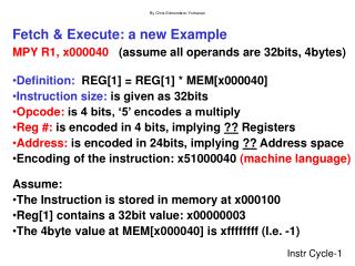
Computer Architecture and the Fetch-Execute Cycle. Von Neumann Architecture. Learning Objectives. Describe basic Von Neumann architecture, identifying the need for and the uses of special registers in the functioning of a processor. Stored Program. John Von Neumann introduced the idea.

E N D
Computer Architecture and the Fetch-Execute Cycle Von Neumann Architecture
Learning Objectives • Describe basic Von Neumann architecture, identifying the need for and the uses of special registers in the functioning of a processor.
Stored Program • John Von Neumann introduced the idea. • Previously data and programs were stored in separate memories. • Von Neumann realised that data and programs are indistinguishable and can, therefore, use the same memory. • This led to the introduction of compilers which accepted text as input and produced binary code as output.
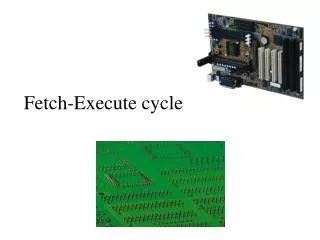
Von Neumann Architecture • Program is stored in memory along with data. • Programs and data are indistinguishable. • Uses a single processor. • Sequential carrying out of instructions.
Registers • Small, permanent storage locations within the CPU used for a particular purpose. • They are only storage locations and do not do anything themselves.
Von Neumann Architecture • Uses a single processor which follows a linear sequence of fetch-decode-execute. • In order to do this, the processor has to use some special registers.
Typical Layout 1 4 3 2
Central Processor Unit (CPU) • Contains: • Arithmetic - Logic Unit (ALU) (also known as the arithmetic unit) • Holds the accumulator. • But also has other circuitry to do its job. • Control Unit • Holds PC & CIR • But also has other circuitry to do its job. • Memory Data Register (MDR) • Memory Address Register (MAR). Remember the registers are simply storage locations. The Control unit and the ALU hold some of these registers but they also have extra circuitry which actually do “things”.
Typical Layout 1 4 3 2
Control Unit • Has circuitry which fetches instructions from memory, decodes them and synchronises the operations before sending signals to other parts of the computer. • Also contains the instruction registers (PC & CIR).
Typical Layout 1 4 3 2
Program Counter (PC)/ Sequence Control Register (SCR) • Stores the address of (so that the control unit can keep track of where to find) the next instruction to be accessed so that a copy of the instruction can be placed in the current instruction register. • The initial contents of the PC is the address of the first instruction of a program and it is copied in by the Loader (see Memory Management Presentation).
Program Counter (PC) • After the address is copied into the MAR the PC is incremented by 1. • At this point it could be said to hold the address of the instruction after the next instruction (as we have not technically started executing the next instruction we should still refer to it as the next instruction). • Assumes that the instructions will be in consecutive locations but if it is a jump instruction the PC will be altered again at the end of the cycle.
PC / SCR • Sometimes the program counter is called the Sequence Control Register (SCR) as the control unit uses its contents to control the sequence of instruction execution.
Typical Layout 1 4 3 2
Memory Address Register (MAR) • Also used to hold / store the memory address (copied from the PC) that contains the instruction to be used next but can also hold the memory address of data needed to execute the next instruction. • After the address has been copied from the PC into the MAR the PC is incremented by 1. • Assumes that the instructions are in consecutive locations but if it is a jump instruction the PC will be altered again at the end of the cycle.
MAR • You may be wondering: why the address is copied into the MAR when it is already in the PC? Why not use the address straight from the PC? You will find out the answer to this in the next presentation (Fetch-Decode-Execute-Reset Cycle Presentation). • Basically the MAR may have to be used to store an address of data needed to execute the next instruction. As no register can hold more than one “thing” at a time the control unit may copy an address of data needed to execute the next instruction over the address of the next instruction in the PC.
Typical Layout 1 4 3 2
Memory Data Register (MDR)/Memory Buffer Register (MBR) • Acts like a buffer and holds anything that is copied from the memory ready for the processor to use it. • This could be the next instruction copied from the memory address held in the MAR but it could also be a piece of data (copied in from an address in memory or back from the instruction in the CIR – see next slide)needed to execute the next instruction.
MDR / MBR • Sometimes the memory data register is called the Memory Buffer Register (MBR) as it acts as a buffer between the primary memory and the processor.
Typical Layout 1 4 3 2
Current Instruction Register (CIR) • Holds the instruction while it is being executed. • The binary code held in the CIR is split into an operation code and an address.
CIR • Again you may be wondering why the instruction is copied into the CIR when it is already in the MDR? • Again you will find out the answer to this in the next presentation (Fetch-Decode-Execute-Reset Cycle Presentation). • Basically the MDR may have to be used to store data needed to execute the next instruction. As no register can hold more than one “thing” at a time the control unit may copy data needed to execute the next instruction over the current instruction in the MDR. So it would no longer “know” what it was supposed to do.
Typical Layout 1 4 3 2
Arithmetic - Logic Unit (ALU) • Internal circuitry processes data here (arithmetic and logical operations). • Arithmetic operations are those that add and subtract numbers, and so on. • Logical operations involve comparing binary patterns and making decisions. • Also contains the accumulator.
Typical Layout 1 4 3 2
Accumulator (ACC) • Stores results of calculations. • All input to and output from processor pass through the accumulator.
Reset • Cycle is reset (restarted) by passing control back to the PC.
Control Unit & ALU • Remember the registers are simply storage locations and do not “do” anything. • The Control Unit “does” everything described in this presentation except for arithmetic and logical operations which is done by the ALU, but even then the Control Unit tells it what to do (i.e. add this to this, compare this with this, etc…).
Typical Layout 1 4 3 2
Typical Layout 1 4 3 2
Typical Layout 1 4 3 2
Typical Layout 1 4 3 2
Typical Layout 1 4 3 2
Plenary • What is Von Neumann architecture?
Von Neumann Architecture • Program is stored in memory along with data. • Programs and data are indistinguishable. • Uses a single processor. • Sequential carrying out of instructions.
Plenary • Explain the purpose of each of the following special registers in a processor. • Program Counter (Sequence Control Register). • Current Instruction Register. • Memory Address Register. • Memory Data Register. • Accumulator.
Program Counter (PC)/ Sequence Control Register (SCR) • Stores the address of (so that the control unit can keep track of where to find) the next instruction to be accessed so that a copy of the instruction can be placed in the current instruction register. • The initial contents of the PC is the address of the first instruction of a program and it is copied in by the Loader (see Memory Management Presentation).
Common confusions with the PC • The PC DOES NOT: • Keep track of the number of programs running. Or • Keep the order in which programs have been called.
Memory Address Register (MAR) • Also used to hold / store the memory address (copied from the PC) that contains the instruction to be used next but can also hold the memory address of data needed to execute the next instruction. • After the address has been copied from the PC into the MAR the PC is incremented by 1. • Assumes that the instructions are in consecutive locations but if it is a jump instruction the PC will be altered again at the end of the cycle.
Memory Data Register (MDR)/Memory Buffer Register (MDR) • Acts like a buffer and holds anything that is copied from the memory ready for the processor to use it. • This could be the next instruction copied from the memory address held in the MAR but it could also be a piece of data (copied in from an address in memory or back from the instruction in the CIR – see next slide)needed to execute the next instruction.
Current Instruction Register (CIR) • Holds the instruction while it is being executed. • The binary code held in the CIR is split into an operation code and an address.
Accumulator (ACC) • Stores results of calculations. • All input to and output from processor pass through the accumulator.