Download
1 / 61
630 likes | 689 Vues
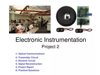
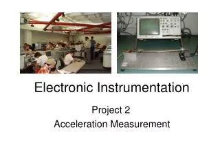
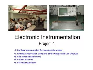
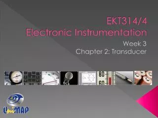
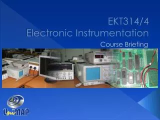
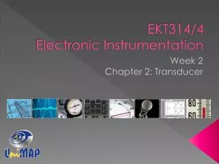
ELECTRONIC INSTRUMENTATION DMT 352/3. Oscilloscope. The Basic Oscilloscope Beam Deflection Vertical Amplifier Horizontal Amplifier Sweep Generators Sampling Oscilloscope Storage Oscilloscope Digital Storage Oscilloscope Attenuators High Impedance Probe. Contents. Introduction.

E N D
ELECTRONIC INSTRUMENTATIONDMT 352/3 Oscilloscope
The Basic Oscilloscope Beam Deflection Vertical Amplifier Horizontal Amplifier Sweep Generators Sampling Oscilloscope Storage Oscilloscope Digital Storage Oscilloscope Attenuators High Impedance Probe Contents
Introduction The oscilloscope is basically a graph-displaying device – it draws a graph of an electrical signal. The graph shows how signals change over time: Y - axis: represents voltage X - axis: represents time Z - axis: represents intensity or brightness (see Fig. 6.1)
Introduction…contd Figure 6.1: X, Y, and Z components of a displayed waveform
Introduction…contd This simple graph can tell you many things about a signal, such as: The time and voltage values of a signal. The frequency and phase. DC and AC components. Spectral analysis. Mathematical analysis. Rise and fall time. How much of the signal is noise and whether the noise is changing with time.
The Basic Oscilloscope Beam Deflection Vertical Amplifier Horizontal Amplifier Sweep Generators Contents
The Basic Oscilloscope A basic Oscilloscope is as shown below. Figure 6.2: Basic Oscilloscope
The Basic Oscilloscope The basic controls are: Brightness – to adjust the intensity of display. Focus – To adjust the focusing of display. Trigger – To select a trigger source. Trace – To select which trace is to be displayed. Timebase (sec/div)– To select the speed which the trace moves across the tube face. Input Level- To adjust the input level. Pos (Position) – To set the position of the trace on the display.
The Basic Oscilloscope Beam Deflection Vertical Amplifier Horizontal Amplifier Sweep Generators Contents
Beam Deflection Figure 6.3: Basic construction of a CRT
Beam Deflection Cathode-ray tubes (CRT) used in oscilloscopes consist of an electron gun, a deflection system, and a fluorescent screen. The electron gun generates electrons and focuses them into a narrow beam. The deflection system moves the beam horizontally and vertically across the screen. The screen is coated with a phosphorous material that glows when struck by the electrons.
Beam Deflection The electron beam is developed, focused, and accelerated by the electron gun. The beam appears on the screen of the CRT as a small, bright dot. The beam of electrons passes through an electrostatic field between two plates. Electrons are negatively charged and that they will be deflected in the direction of the electric force (from negative to positive). This deflection causes the electrons to follow a curved path while in the electrostatic field.
Beam Deflection When the electrons leave the electrostatic field, they will take a straight path to the screen at the angle at which they left the field. The beam can be positioned anywhere on the screen by adjusting the controls marked horizontal position and vertical position. When the horizontal and vertical position controls are set to their midpoint position, the deflection voltages divide equally across both halves of the potentiometers. There is therefore no deflection of the beam; it simply travels along the axis of the CRT and strikes the centre of the screen.
Beam Deflection Adjusting the horizontal and vertical position control deflect the beam to any desired position on the screen. Factors influencing deflection angle: Length of the deflection field. Spacing between the deflection plates. The difference of potential between the plates. The accelerating voltage on the second anode.
Beam Deflection Length of the deflection plate The longer deflection plates can bend the beam to a greater deflection angle.
Beam Deflection Spacing between the deflection plates The closer together the plates, the more effect the electric force has on the deflection angle of the electron beam.
Beam Deflection The difference of potential between the plates The greater the potential, the wider the deflection angle.
Beam Deflection The accelerating voltage on the second anode The faster the electrons are moving, the smaller their deflection angle will be.
The Basic Oscilloscope Beam Deflection Vertical Amplifier Horizontal Amplifier Sweep Generators Contents
Vertical Amplifiers The vertical amplifier is the principal factor in determining the sensitivity and bandwidth of an oscilloscope. The gain of the vertical amplifier determines the smallest signal that the oscilloscope can be satisfactory reproduce on the CRT screen. The sensitivity of an oscilloscope is directly proportional to gain of the vertical amplifier; that is, as gain increases, sensitivity increases, which allows us to observe smaller-amplitude signals.
Vertical Amplifiers The vertical sensitivity is a measure of how much the electron beam will be deflected for a specified input signal. Bandwidth of an oscilloscope determines the range of frequencies that can be accurately reproduced on the CRT screen. The greater the bandwidth, the wider the range of frequencies that can be observed with the instrument.
The Basic Oscilloscope Beam Deflection Vertical Amplifier Horizontal Amplifier Sweep Generators Contents
Horizontal Amplifiers The horizontal amplifier basically serves two purposes: When the oscilloscope is being used in the ordinary mode of operation to display a signal applied to the vertical input, the horizontal amplifier will amplify the sweep generator output. When the oscilloscope is being used in the X-Y mode, the signal applied to the horizontal input terminal will be amplified by the horizontal amplifier.
The Basic Oscilloscope Beam Deflection Vertical Amplifier Horizontal Amplifier Sweep Generators Contents
Sweep Generators Oscilloscopes are used to display a waveform that varies as a function of time. If the waveform is to be accurately reproduced, the beam must have a constant velocity. Since the beam velocity is a function of the deflecting, voltage must increase linearity with time. A voltage with this characteristic is called a ramp voltage. If the voltage decreases rapidly to zero with waveform repeatedly reproduced, as shown in Figure 6.4, the pattern is generally called a sawtooth waveform.
Sweep Generators Figure 6.4: Typical sawtooth waveform applied to the horizontal deflection plates.
Sweep Generators During the sweep time, Ts the beam moves from left to right across the CRT screen. The beam is deflected to the right by the increasing amplitude of the ramp voltage and the fact that the positive voltage attracts the negative electrons. During retrace time, Tr the beam returns quickly to the left side of the screen. The control grid is generally “gated off”, which blanks out the beam during retrace and prevents an undesirable retrace pattern from appearing on the screen.
Sampling Oscilloscope Storage Oscilloscope Digital Storage Oscilloscope Attenuators High Impedance Probe Contents
Sampling Oscilloscope To display recurrent (repetition) signals whose frequencies are higher than the limits of the ultra-wideband (high-frequency) scopes, sampling techniques must be used. With these techniques, the signal is reconstructed for display from sequential samples of its waveform. A sampling scope is analogous to a stroboscope, a device that’s permits visual observation of rapidly rotating machinery.
Sampling Oscilloscope A sampling system measures the amplitude of a small portion of the waveform and displays this instantaneous amplitude on the CRT in the form of a dot. After displaying the dot, the beam is shut off and move horizontally over a short distance. During this time interval, the scope measures another sample of the input waveform, but at another position in the cycle. Now the scope displays the new instantaneous amplitude as another dot, position horizontally a very short distance from the first dot.
Sampling Oscilloscope In this way, the oscilloscope plots the input waveform point by point, using as many as 1000 samples to reconstruct the original waveform (see Fig 6.5). The sample frequency may be as low as one-hundredth (1/100) of the input signal frequency. i.e. If input signal has a frequency of 1GHz (1000MHz), the required BW of the oscilloscope amplifier need be only 10MHz.
Sampling Oscilloscope Figure 6.5: Relationship between input waveform, sampling pulses, and scope display in sampling
Sampling Oscilloscope Storage Oscilloscope Digital Storage Oscilloscope Attenuators High Impedance Probe Contents
Storage Oscilloscope An extra feature available on some analogue scopes is called 'storage'. This feature allows the trace pattern (waveform) that normally decays in a fraction of a second to remain on the screen for several minutes or longer. Two storage techniques are used in oscilloscope CRT’s, mesh storage and phosphor storage. A mesh-storage CRT uses a dielectric material deposited on a storage mesh as the storage target. This mesh is placed between the deflection plates and the standard phosphor target in the CRT.
Storage Oscilloscope The writing beam, which is the focused electron beam, charges the dielectric material positively where hit. The storage target is then hit with low velocity electrons from a flood gun and the positively charged areas of the storage target allow these electrons to pass through to the standard phosphor target and thereby reproduced the stored image on the screen. Thus the mesh storage has both a storage target and a phosphor display target. The phosphor storage CRT uses a thin layer of phosphor to serve both as the storage and the display element.
Storage Oscilloscope Figure 6.6: Basic elements of Storage Mesh CRT
Storage Oscilloscope Mesh Storage: A mesh storage CRT (see Figure 6.6) contains a dielectric material deposited on a storage mesh, a collector mesh, flood guns and a collimator, in addition to all elements of a standard CRT. The storage target, a thin deposition of a dielectric material (such as Magnesium Fluoride) on the storage mesh, make use a property known as secondary emission. The writing gun etches a positively charged pattern on the storage mesh or target by knocking off secondary emission electrons.
Storage Oscilloscope Mesh Storage: …(contd) This positively charged pattern remains exactly in the position where it is deposited. In order to make a pattern visible, a special electron gun (flood gun) is switched on. The electron path are adjusted by the collimator electrode (as shown in Fig 6.7).
Storage Oscilloscope Figure 6.7: Storage Mesh CRT
Storage Oscilloscope Mesh Storage: …(contd) Most of the electrons are stopped and collected by the collector mesh. Only electrons near the stored positive charge are pulled to the storage target with sufficient force to hit the phosphor screen (see Figure 6.7) The CRT will now display the signal and it will remain visible as long as the flood guns operate. To erase the pattern on the storage mesh, a negative voltage is applied to neutralize the stored positive charge.
Storage Oscilloscope Figure 6.7: Display of stored charged pattern on a mesh-storage
Sampling Oscilloscope Storage Oscilloscope Digital Storage Oscilloscope Attenuators High Impedance Probe Contents
Digital Storage Oscilloscope The digital storage oscilloscope, or DSO, is now the preferred type for most industrial applications. It replaces the unreliable storage method used in analogue storage scopes with digital memory, which can store data as long as required without degradation. It also allows complex processing of the signal by high-speed digital signal processing circuits. The vertical input, instead of driving the vertical amplifier, is digitized by an analog to digital converter to create a data set that is stored in the memory of a microprocessor.
Digital Storage Oscilloscope The data set is processed and then sent to the display, which in early DSOs was a cathode ray tube, but is now more likely to be an LCD flat panel. The data set can be sent over a LAN or a WAN for processing or archiving. The screen image can be directly recorded on paper by means of an attached printer or plotter, without the need for an oscilloscope camera.
Digital Storage Oscilloscope The scope's own signal analysis software can extract many useful time-domain features (e.g. rise time, pulse width, amplitude), frequency spectra, histograms and statistics, persistence maps, and a large number of parameters meaningful to engineers in specialized fields such as telecommunications, disk drive analysis and power electronics. The oscilloscope is able to vary its time base to precisely time its sample, thus building up the picture of the signal over the subsequent repeats of the signal.
Digital Storage Oscilloscope This type of scope is frequently used for very high speed communication because it allows for a very high "sample rate" and low amplitude noise compared to traditional real-time scopes. A digital storage oscilloscope manufactured by Agilent Technologies
Digital Storage Oscilloscope Advantages over the analogue oscilloscope: Brighter and bigger display with color to distinguish multiple traces. Equivalent time sampling and Average across consecutive samples or scans lead to higher resolution down to µV. Peak detection. Pre-trigger. Easy pan and zoom across multiple stored traces allows beginners to work without a trigger. This needs a fast reaction of the display (some scopes have 1 ms delay). The knobs have to be large and turn smoothly.
Digital Storage Oscilloscope Advantages over the analogue oscilloscope…contd Also slow traces like the temperature variation across a day can be recorded. The memory of the oscilloscope can be arranged not only as a one-dimensional list but also as a two-dimensional array to simulate a phosphorus screen. The digital technique allows a quantitative analysis.
Sampling Oscilloscope Storage Oscilloscope Digital Storage Oscilloscope Attenuators High Impedance Probe Contents
Attenuators Function – to reduce the amplitude of the input signals by a selector factor F, before such signals are applied to the preamplifier/amplifier section. Figure 6.8: vertical deflection subsystem