DMT 121 – ELECTRONIC DEVICES
DMT 121 – ELECTRONIC DEVICES. Chapter 4 DC Biasing – Bipolar Junction Transistors (BJTs). OBJECTIVES. Discuss the concept of dc biasing of a transistor Analyze voltage-divider bias, base bias, emitter bias and collector-feedback bias circuits.


DMT 121 – ELECTRONIC DEVICES
E N D
Presentation Transcript
DMT 121 – ELECTRONIC DEVICES Chapter 4 DC Biasing – Bipolar Junction Transistors (BJTs)
OBJECTIVES • Discuss the concept of dc biasing of a transistor • Analyze voltage-divider bias, base bias, emitter bias and collector-feedback bias circuits. • Basic troubleshooting for transistor bias circuits.
INTRODUCTION • For the transistor to properly operate it must be biased. There are several methods to establish the DC operating point. • We will discuss some of the methods used for biasing transistors as well as troubleshooting methods used for transistor bias circuits.
BIASING & 3 STATES OF OPERATION • Active or Linear Region Operation Base–Emitter junction is forward biased Base–Collector junction is reverse biased • Cutoff Region Operation Base–Emitter junction is reverse biased • Saturation Region Operation Base–Emitter junction is forward biased Base–Collector junction is forward biased
DC OPERATING POINT The goal of amplification in most cases is to increase the amplitude of an ac signal without altering it.
DC OPERATING POINT For a transistor circuit to amplify it must be properly biased with dc voltages. The dc operating point between saturation and cutoff is called the Q-point. The goal is to set the Q-point such that that it does not go into saturation or cutoff when an a ac signal is applied. IB IC and VCE IB IC and VCE
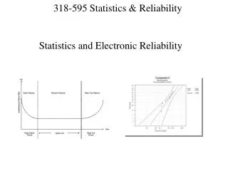
DC OPERATING POINT Recall that the collector characteristic curves graphically show the relationship of collector current and VCE for different base currents. With the dc load linesuperimposed across the collector curves for this particular transistor we see that 30 mA (IB = 300 A) of collector current is best for maximum amplification, giving equal amount above and below the Q-point. Note that this is three different scenarios of collector current being viewed simultaneously.
DC OPERATING POINT With a good Q-point established, look at the effect of superimposed ac voltage has on the circuit. Note the collector current swings do not exceed the limits of operation (saturation and cutoff). However, as you might already know, applying too much ac voltage to the base would result in driving the collector current into saturation or cutoff resulting in a distorted or clipped waveform.
WAVEFORM DISTORTION Graphical load line illustration of a transistor being driven into saturation and/orcutoff
FIXED-BIAS (BASE-BIAS) CIRCUIT • Simplest transistor bias configuration. • Commonly used in relay driver circuits. • Extremely beta-dependant and very unstable Fixed-bias circuit. DC equivalent circuit.
FIXED-BIAS (BASE-BIAS) CIRCUIT Measuring VCE and VC. Collector – Emitter loop Base – Emitter loop VCC – ICRC – VCE = 0 VCE = VCC – ICRC; then = VC – VE since VE = 0 VCE = VC VBE = VB – VE (since VE = 0) VBE = VB Since IC = IB, then Sensitive to Beta
EMITER BIAS • Use both a positive and a negative supply voltage on emitter or it just contain an emitter resistor to improve stability level over fixed – bias configuration. An npn transistor with emitter bias. Polarities are reversed for a pnp transistor. Single subscripts indicate voltages with respect to ground. BJT bias circuit with emitter resistor.
EMITER BIAS – only RE Collector – Emitter loop VCC – ICRC – VCE – IERE = 0 IE IC VCC – ICRC – VCE –ICRE =0 VCC – VCE = IC (RC + RE) BJT bias circuit with emitter resistor. Base – Emitter loop VCC – IBRB – VBE – IERE = 0 IE = ( + 1) IB Then, VCC – IBRB – VBE – ( + 1)IBRE = 0. Since IC = IB, so IC also equivalent to Less sensitivity to beta
EMITER BIAS –RE + DC Voltage Supply Collector – Emitter loop VCC – ICRC – VCE – IERE + VEE = 0 IE IC VCC – ICRC – VCE –ICRE + VEE =0 VCC – VCE + VEE = IC (RC + RE) Base – Emitter loop VEE + IBRB + VBE + IERE = 0 IE = ( + 1) IB Then, VEE + IBRB + VBE + ( + 1)IBRE = 0. Less sensitivity to beta
EMITTER BIAS - Summary With DC Voltage supply + Resistor at Emitter With only Resistor at Emitter Previous analysis we use IE = ( + 1) IB; but if use IE IC IB, then from previous slide we can get. If RE >>> RB/ then we can drop RB/ in equation Less sensitivity to beta or independent to beta OR we also can use ( + 1) to get the same result. If VEE >>> VBE then Independent to VBE
EXAMPLE Determine VCEQ and IE for the network as shown in Fig. -VEE + IERE + VCE = 0 IE = ( + 1)IB VCEQ = VEE – (+1)RE = 20V – (91)(45.73)(2k) = 11.68 mA IE = 4.16 mA VEE – IBRB – VBE – IERE = 0 IE = ( + 1)IB
EMITTER BIAS - Summary • Adding RE to the emitter improves the stability of a transistor. • Stabilityrefers to a bias circuit in which the currents and voltages will remain fairly constant for a wide range of temperatures and transistor Beta () values.
VOLTAGE DIVIDER BIAS • The most widely used type of bias circuit. Only one power supply is needed and voltage-divider bias is more stable ( independent) than other bias types. • Two methods of analysis, exact and approximate analysis
VOLTAGE DIVIDER BIAS – Exact Analysis Determining RTH. To determine RTH The voltage source is replaced by a short-circuit equivalent, resulting…….. RTH = R1ǁ R2
To determine ETH The voltage source VCC remained on the network and the open circuit Thevenin voltage can be determined. VOLTAGE DIVIDER BIAS – Exact Analysis Determining ETH.
VOLTAGE DIVIDER BIAS – Exact Analysis The Thevenin network is then redrawn and IBQ can be determined by applying Kirchoff’s voltage law. ETH – IBRTH – VBE – IERE = 0, ….substitute IE = ( + 1) IB…..then Almost similar with emitter bias Voltage differences over resistance.
VOLTAGE DIVIDER BIAS – Exact Analysis IC = IB ; IE = ( + 1) IB IB Substituting between these OR equation in previous slide (from derivation), resulting : If RE >>> RTH/, then… Independent to Beta
VOLTAGE DIVIDER BIAS – Exact Analysis Once IB is known, the rest of the parameters can be determined. VCE = VCC – IC (RC + RE) The remaining equations VE, VC and VB are also similar as obtained in emitter bias configuration. Voltage-divider bias configuration.
VOLTAGE DIVIDER BIAS – Approximate Analysis and Ri = ( + 1)RE RE with condition RE 10R2 Partial-bias circuit for calculating the approximate base voltage VB. If beta times the value RE is at least 10x the value R2, the approximate approach can be applied with high accuracy. Ri = equivalent transistor between base and ground for transistor with an emitter resistor RE
VOLTAGE DIVIDER BIAS – Approximate Analysis Once VB is determined, the level of VE can be calculated. VE = VB – VBE And emitter current and IC IE VCE = VCC –ICRC –IERE but since IE IC VCE= VCC – IE (RC + RE) Partial-bias circuit for calculating the approximate base voltage VB.
VC Collector Feedback Bias (DC Bias with Voltage Feedback) • An improved level of stability can also be obtained by introducing a feedback path from collector to base. • If IC tries to increase, it drops more voltage across RC, thereby causing VC to decrease. When VC decrease, there is a decrease voltage across RB, which decrease IB. The decrease in IB produce less IC which in turn, drops less voltage across RC and thus offsets the decrease in VC. • These feedbacks keep the Q-point stable. IC VRC VC VRB IB IC VRC offset the decrease in VC
Base – Emitter Loop VCC – IC'RC – IBRB – VBE – IERE = 0 Actual case IC' = IC + IB Approximation can be employed : IC' IC = IB and IE IC VCC – VBE - IB (RC + RE) – IBRB = 0 Solving for IB, yields Collector Feedback Bias (DC Bias with Voltage Feedback)
Collector – Emitter Loop VCC – IC'RC – VCE – IERE = 0 Approximation can be employed : IC' IC and IE IC VCC – VCE - IC (RC + RE) = 0 VCE = VCC – IC (RC + RE) Collector Feedback Bias (DC Bias with Voltage Feedback)
TROUBLESHOOTING Shown is a typical voltage divider circuit with correct voltage readings. Knowing these voltages are required before logical troubleshooting can be applied. We will discuss some of the faults and symptoms.
TROUBLESHOOTING R1 Open With no bias the transistor is in cutoff. Base voltage goes down to 0V. Collector voltage goes up to 10 V (VCC). Emitter voltage goes down to 0V.
TROUBLESHOOTING Resistor RE Open: Transistor is in cutoff. Base reading voltage will stay approximately the same. Collector voltage goes up to 10V(VCC). Emitter voltage will be approximately the base voltage + 0.7V.
TROUBLESHOOTING Base Open Internally: Transistor is in cutoff. Base voltage stays approximately the same. Collector voltage goes up to 10V(VCC). Emitter voltage goes down to 0V.
TROUBLESHOOTING Open BE Junction: Transistor is in cutoff. Base voltage stays approximately the same. Collector voltage goes up to 10V(VCC) Emitter voltage goes down to 0V.
TROUBLESHOOTING Open BC Junction: Base voltage goes down to 1.11V because of more base current flow through emitter. Collector voltage goes up to 10V (VCC). Emitter voltage will drop to 0.41V because of small current flow from forward biased base-emitter junction.
TROUBLESHOOTING RC Open: Base voltage goes down to 1.11V because of more current flow through the emitter. Collector voltage will drop to 0.41V because of current flow from forward biased collector-base junction. Emitter voltage will drop to 0.41V because of small current flow from forward biased base-emitter junction.
TROUBLESHOOTING R2 Open: Transistor pushed close to or into saturation. Base voltage goes up slightly to 3.83V because of increased bias. Emitter voltage goes up to 3.13V because of increased current. Collector voltage goes down because of increased conduction of transistor.
SUMMARY • The purpose of biasing is to establish a stable operating point (Q-point). • The Q-point is the best point for operation of a transistor for a given collector current. • The dc load line helps to establish the Q-point for a given collector current. • The linear region of a transistor is the region of operation within saturation and cutoff.
SUMMARY • Voltage-divider bias is most widely used because it is stable and uses only one voltage supply • Base bias is very unstable because it is dependant. • Emitter bias is stable but require two voltage supplies. • Collector-back is relatively stable when compared to base bias, but not as stable as voltage-divider bias.