Open Systems Interconnect (OSI) Model
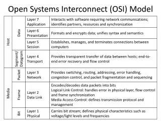
Open Systems Interconnect (OSI) Model. Controller Area Network Standard. Defines Physical Layer (L1) Defines Data Link Layer (L2) Defines how to Transport (L4) small (8 bytes) datagrams No flow control (L3 and L4) No sequencing and fragmentation (L3)

Open Systems Interconnect (OSI) Model
E N D
Presentation Transcript
Controller Area Network Standard • Defines Physical Layer (L1) • Defines Data Link Layer (L2) • Defines how to Transport (L4) small (8 bytes) datagrams • No flow control (L3 and L4) • No sequencing and fragmentation (L3) • No Session (L5) or Presentation (L6) specs • Different Higher Layer Protocols (HLPs) handle the rest
Common CAN HLPs • CanKingdom • CANopen • CCP/XCP • DeviceNet • SAE J1939 • OSEK • SDS • These define the “Object” Layer (layers not defined by the CAN standard)
CAN Physical Layer – Voltages • Open collector (wired-OR); NRZ • Dominant bits are logical 0 • Recessive bits are logical 1 • Provides arbitration free transmission If A transmits recessive (1) and sees dominant (0) from B, A knows collision occurred and stops transmitting (will retry 6 clock cycles after end of dominant message)
CAN Physical Layer – Timing • Each node has its own clock • Synchronization done by dividing bit time into four segments • Phases 1 & 2 adjusted based on network and node conditions • Sample between Phase 1 & 2 Bit Time Sync Propagation Phase Segment 1 Phase Segment 2 Clock
CAN Data Link Layer • Specifies four message types • Data: contains data for transmission • Data Request (Remote): requests transmission of a specific identifier • Error: transmitted by any node detecting an error • Overload: injects a delay between data and/or remote frames
CAN Data Frames For Data Request RTR = 1 (recessive) and DLC = 0 (data field empty)
Error Frames • Active error generated by transmitter • Passive error generated by receiver • Error Types • Bit: Send recessive, read dominant • Stuff: more than 5 consecutive bits of same polarity • CRC: computed and received CRCs not equal • Form: invalid bits in field • ACK: no acknowledgement from receiver
Overload Frames • Two overload conditions • Internal conditions of receiver – it can’t keep up • Dominant bit detected during expected intermission (interframe space)
Byte Data Link Controller (BDLC) • Physical Layer has three forms • 2-wire: 10.4 Kbps, UART, NRZ (Chrysler) • 2-wire: 41.6 Kbps pulse width modulated (Ford) • 1-wire: 10.4 Kbps variable pulse width (GM) • High level 4.25-20 V; Low level < 3.5 V • Buses use weak pull-down, driver pulls it high • High signals are dominant • High and low values are bit symbols with specific times
BDLC – Data Link Layer SOF Header Data CRC EOD IFR CRC EOF 3 byte headers contain destination and source addresses