Innovative Design of a Portable Bridge: Engineering Solutions for Transportation Challenges
This paper discusses the design and engineering of a portable bridge inspired by various machines, such as bridge-laying tanks. The objective was to create a vehicle capable of carrying and constructing a bridge over a gap, using lightweight materials while retaining strength. The design includes two vehicles featuring multiple axles and bicycle frames to support the bridge. By optimizing the structure in a see-saw motion, it achieved stability and mobility, demonstrating practical applications of mechanical principles and innovative problem-solving during a timed competition.

Innovative Design of a Portable Bridge: Engineering Solutions for Transportation Challenges
E N D
Presentation Transcript
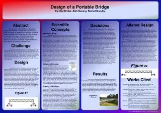
Design of a Portable Bridge By: Mat Drotar, AishNarang, Rachel Murphy Scientific Concepts Several different types of machines are currently in use that utilize the ability to carry, construct a bridge, and pick it back up again after it has been crossed. An example of this type of machine would be the bridge laying tanks currently in use by several different militaries around the world ("WWII”). These machines work by pulling up to a gap, deploying a foldable bridge and allowing those who need to cross to do so ( "WWII”). But, since in Junkyard Wars the teams had to pick up their bridges again and the materials that they had were not strong enough to support a hinge in the middle of the bridge, a design similar to this could not have worked. The weakness of the flimsy bikes was the main problem for The Mothers of Invention. If we were to use their design, we would engineer a different vehicle for transporting the bridge. Instead of using flimsy bicycles with only two wheels, we would engineer two vehicles that consisted of a platform that sat on top of two axles. On either end of each axle there would be a car wheel that can support more weight than the bicycle wheels that were used. On the rear axle of each vehicle there would be two gears attached. On top of the platform would be the frame of two bicycles. The bike chains would run from the cranks of the bicycles, through the platform, down and around the gears attached to the rear axles. The functionality of the vehicle would be similar to a bike in that it would require the passengers to pedal to move the vehicle. Since the course is in a straight line, a turning function is not required. There would be identical pivot wheels in our design to those in their design attached to the bridge that are able to be adjusted in order to allow the bridge to pivot. We would use the same bridge design as the Mothers of Invention. However, since the vehicles would weigh more the addition of another beam used as the bridge might be necessary because the current bridge may not be able to support the extra weight. Altered Design Abstract Decisions The purpose of the Mothers of Invention design was to create a vehicle that can hold up a bridge and carry all members of the group through a circuit, including a five meter gap. In order to create their vehicle, they had only ten hours and were allowed to use only the materials found in the junkyard. In the end, the design completed the task with a few minor problems along the way. Throughout the competition the team was forced to make decisions about the design and functionality of their machine. They decided what design to use, what materials to use, and what kind of vehicles to use. When the challenge first started they decided to use a design that utilized four bicycles. The four bikes would be attached into two groups of two bikes each. Then, a group of bikes would be attached to either end of the bike. Pivoting wheels would be added two and a half meters from each end of the bridge to allow the bridge and bikes on the other side to pivot. The bridge had to work in a see-saw motion when crossing the gap. This was tested by having three members sit on one side of the bridge while one member remained sitting on the other side of the bridge, imitating the weight of the bikes on both sides of the bridge. This test helped them discover the length of the bridge in order to properly withstand the weight of the bikes when carried over the gap. Also, the length then determined where the pivoting wheels should be placed in order to create the see-saw motion. In their design they had to create a strong, yet lightweight structure so the bridge would be sturdy but easy to maneuver. Using an existing steel support that could be used as a truss bridge, they created the platform for the bridge. The steel support was ten meters long and approximately half of a meter in width. The steel beam was an effective material to use for the bridge’s platform due to the triangle support system that is also used in a truss bridge. The triangle is a shape that is used to support and create sturdy structures, so it was a good way to create a strong bridge. To make the bridge mobile, they fixed up four lightweight bikes from the junk yard to be used as vehicles. This was important because they needed to keep the weight down and the use of bicycles helped the vehicle move without the heavy weight of an engine. Wheel and Axle: The wheel and axle is one of the six simple machines used to multiply the force one applied and to multiple the distance traveled (Willis). It is also considered a first class lever. This means that an equal effort has to be applied to lift a certain amount or load (Willis). This simple machine is based off of the law: “The force applied multiplied by the radius of the wheel equals the load” (Willis). Developed in the ancient times, the wheel and axle is ranked as one of the most important inventions in history. For a wheel and axle design to work, one must follow a series of steps. The first step is by applying a force on the wheel, where the radius, R, is larger than the axle (Willis). This is demonstrated in the Figure 2. Next, the force is transmitted to the axle which has a radius, r (Willis). The resultant force must be bigger than the force one initially applies, and ends up doing some of the work. This ‘helpful’ force is bigger than the original force applied by a factor of R/r (Willis). When set equal to each other: initial force applied multiplied by the radius of the wheel is equal to the load multiplied by the radius of the axle (Chirikjian). In other terms, yet meaning the same concept, initial force divided by the radius of the wheel is equal to the radius of the axle. In order to solve for a missing part, one can use either of these equations to get an answer. Like on the bicycles used for the Mother’s of Invention design, the tires contained teeth or cogs around the circumference of the wheel. This helps add speed when the wheel and axle machine are put into motion. Challenge The objective of this episode of Junk Yard Wars was to design a mobile bridge within the span of ten hours with the materials founds in the junk yard. The goal was to go through a circuit, including getting over a five meter gap distance. When crossing the gap, all four members of the group were required to cross the gap, retrieve a flag, turn around, cross the gap again, and reach the finish line. The group must design the bridge in a way that the bridge could be picked up and set down across the gap again; leaving the bridge across the five meter gap as they go through the course was not allowed. Design Figure 2. Wheel and Axle Balance of Forces:Newton’s first law of motion, “An object at rest stays at rest and an object in motion stays in motion with the same speed and in the same direction unless acted upon by an unbalanced force” is the perfect description of a see-saw (The Physics Classroom). A see-saw is a lever, meaning it is a device made up of a long object fixed on a moving point. The moving point is called the fulcrum, which is centered in the middle of the see-saw (NASA). The net torque is the determination of the balance of the see-saw. The see-saw is balanced (at equilibrium) when there is no net torque. Torque is the force that produces rotation at the center of the device (NASA). The net torque is found through the equation: force x distance, or mass x distance (NASA). The force applied to each side (mass) multiplied by the distance from the fulcrum will result in the net torque. In order for the see-saw to achieve no net torque and be balanced, side A must equal side B. This can be demonstrated by the equation (M1)(D1)=(M2)(D2). Figure#4 The Mothers of Invention designed a ten-meter bridge with two bicycles attached to each side. Two pivoting wheels placed five meters apart from each other and two and a half meters from each end were attached underneath the bridge. To get all four group members across, they rode the bikes to the edge of the gap, the pivoting wheel two and a half meters from the back bicycles was deployed, the two team members on the front bikes ran to the back bicycles, and the bridge was moved forward until the front two bikes were hovering over the other side. Then the pivoting wheel was drawn back up, and two team members crossed the bridge while the other two members remained seated on the back bikes. When the two members reached the other side, they sat on the front bikes while the remaining two members crossed the bridge. Once all four members were across, the other pivoting wheel was deployed and the back bikes and the bridge were moved over the gap and onto the other side. Once the device was across, two team members went to the back bikes and the bridge was taken to obtain the flag. Then the machine was turned around and the gap was crossed again using the same process. Results In the end, the Mothers of Invention’s design crossed and re-crossed the gap successfully, completing the circuit. Though their design successfully completed the challenge, their design was not as efficient as the other team’s design. Due to the amount of weight put on the bicycles and their thin wheels, the team members were not able to pedal the bikes to the gap. Instead, they had to carry or drag the bikes and the bridge, slowing down the moving process. Plus the narrow bridge required the team members to cross slowly, which took a long length of time. The Mothers of Invention’s design was successful, but executing the challenge with their design was more time consuming than desired. These flaws led to the group’s loss in the competition. Works Cited "Balanced and Unbalanced Forces." The Physics Classroom. The Physics Classroom, 2011. Web. 12 Jan. 2011. <http://www.physicsclassroom.com/class/newtlaws/u2l1d.cfm >.“Balance Of Forces.” NASA. NASA, 17 Feb. 2010. Web. 7 Jan. 2011. <http://www.grc.nasa.gov/WW W/k 12/WindTunnel/Activities/balance_of_forces.html>.Chirikjian, Gregory S. "Wheel and axle." World Book Advanced. World Book, 2011. Web. 10 Jan. 2011."How Bridges Work." Perrin Hall Brunson Web Development and Design. Web. 10 Jan. 2011. <http://www.perrinhall.com/projects/bridges/how_bridges_wor k.html>.Willis, Bill. "The Wheel and Axle." Worsley School OnLine... the Website for Worsley School. 2002. Web. 10 Jan. 2011. <http://www.worsleyschool.net/science/files/wheel/andaxle.ht ml>. "WWII - STRANGE GERMAN PANTHER TANK BRIDGE LAYING VEHICLE."StrangeCosmos.com. Web. 22 Jan. 2011. <http://strangerockstars.com/content/item/136978.html> Physics of Bridges: There are several different theories of physics that apply to bridges. One that occurs in the materials of a bridge is compression ("How Bridges Work.“). Tension also occurs in bridges ("How Bridges Work.“). Tension and compression are two similar actions that occur to the materials in a bridge. When weight is placed on a bridge, certain beams begin to experience tension and compression. One side of these beams sags and experiences tension ("How Bridges Work.“). When tension occurs in a material, the molecules are pulled apart("How Bridges Work.“). Compression occurs on the opposite side of the one under tension. When compression occurs the molecules are pushed together and the material shortens in length ("How Bridges Work.“). These two forces acting together force a beam to beam and make it look as if it’s sagging. A good bridge dissipates these forces to help add strength and make the bridge be able to support more weight ("How Bridges Work.“). A truss bridge is best at dissipating the forces of compression and tension ("How Bridges Work.“). The bridge used by The Mothers of Invention team was an example of a truss bridge. This was a good choice because truss bridges are the most supportive. Figure #1 Figure #3 Truss Bridge