Internal Combustion Engine
Internal Combustion Engine. Operation & Design. Learning objectives. Learning objective. Internal Combustion Engine Operation. It is important to know and understand that there are several types of internal combustion engines but they all operate on the same basic principle or concept.

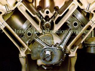
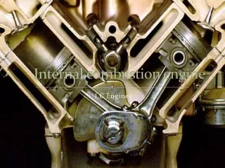
Internal Combustion Engine
E N D
Presentation Transcript
Internal CombustionEngine Operation & Design
Internal Combustion Engine Operation • It is important to know and understand that there are several types of internal combustion engines but they all operate on the same basic principle or concept. • Types of Internal Combustion Engines • Two Stroke (Lawn Equipment, R.C. Hobby, Dirt Bikes, and Small Boats) • Four Stroke (Cars, Trucks, SUV, Generators) • Rotary (Wankle Design Mazda RX 8, Helicopters) • Turbine (Jets) • Rockets (Space Flight)
Internal Combustion Engine Operation Two Stroke, Four Stroke, Rotary, Turbine, & Rockets What do these Internal Combustion Engines Have in Common? While the overall design of these internal combustion engines is vastly different they all operate or function by converting an fuel/air mixture into heat inside a combustion chamber. The purpose of the internal combustion engine is to convert stored chemical energy into kinetic energy or the energy of motion. In this unit we will focus our attention on the four stroke internal combustion engine because most highway automobiles operate on the 4 stroke cycle.
Fuel & The four stroke engine There are 3 common fuels used in four stroke engines • Diesel Fuel • Ethanol • Gasoline
Fuel & The four stroke engine Diesel Fuel Named after Rudolf Diesel the inventor of the four stroke diesel engine in 1894, Diesel fuel is a type oil that has a relatively low flash point of about 205ºF. Diesel oil will ignite within the combustion chamber as aresult of the extreme heat generated on the compression stroke of the four stroke cycle. Because of diesel fuels low flash point and the diesel engines high compression ratio diesel engines do not require ignition systems for combustion to take place. Instead they use glow plugs to raise the temperature inside the combustion chamber on the first cycle of the four stroke process. Diesel Fuel is the leading fuel for heavy equipment like trains, heavy trucks, ocean vessels, power generators, and tractors.
Fuel & The four stroke engine Ethanol Ethanol is another name for denatured alcohol or pure grain alcohol. Ethanol was one of the first alternatives to diesel fuel. One of the earliest mass produced vehicles to operate on Ethanol was Henry Fords Model T. Prohibition in the 1920’s included alcohol produced for fuel so after 7 years of production Henry Ford switched to gasoline to power his engine. After this ethanol was not used as a common fuel until the late 1990’s when it was used as a 10% additive to gasoline After the turn of the century fuel manufacturers began to market E85 a mixture of 85% ethanol to 15% gasoline. While ethanol will work in modern gasoline engines it will corrode the fuel delivery components. Ethanol has once again claimed it status as an alternative fuel in passenger vehicles.
Fuel & The four stroke engine Gasoline Gasoline is the result of distilling crude oil. This process breaks crude oil down into several components including tar, grease, refined oil, kerosene, diesel oil, gasoline, natural gas, and other light gasses. Gasoline is most commonly used in light trucks and passenger vehicles. Gasoline has a much higher flash point of approximately 495ºF. Gasoline engines require an ignition system to ignite the air fuel mixture. Ignition systems include spark plugs, ignition wires, distributor, and an ignition coils. Even though gasoline is not the most efficient type of engine they lead the industry because they are versatile, quite, and their tailpipe emissions or exhaust are cleaner than most.
Fuel & The four stroke engine Comparing the Power Stroke of Diesel Vs. Gasoline Fuel Injector Spark Plug DIESEL ENGINE GASOLINE ENGINE A fuel injector introduces fuel into the combustion chamber at the start of the power stroke. The heat from generated from the previous stroke ignites the fuel forcing the piston downward. The compressed fuel air mixture is ignited by a spark from the spark plug at the start of the power stroke forcing the piston downward.
The four stroke Cycle • CYCLE:A term that refers to the repetitive function of a mechanical system. The cycle is a function the is performed repeatedly. • Stroke:One linear motion of a piston from TDC to BDC or from BDC to TDC. There are 4 strokes for every cycle in an internal combustion engine. • TDC: Top Dead Center when the piston is at its absolute highest point of a given stroke. • BDC: Bottom Dead Center when the piston is at its absolute lowest point of a given stroke.
The four stroke Cycle What Are The Four Strokes INTAKE STROKE COMPRESSION STROKE POWER STROKE EXHAUST STROKE 1ST STROKE 2ND STROKE 3RD STROKE 4TH STROKE
The four stroke Cycle Intake Stroke • First stroke of cycle • Piston moves from TDC to BDC • Intake valve open • Exhaust valve closed • On the intake stroke a precision mixture of fuel & air are drawn into the combustion chamber through the open intake valve. The Intake stroke may also be called the induction stroke. Exhaust Valve Closed Intake Valve Open Air Fuel Mixture Is Drawn Into Combustion Chamber Crankshaft Rotates 180º Piston Moves Downward
The four stroke Cycle Compression Stroke • Second stroke of cycle • Piston moves from BDC to TDC • Intake & exhaust valves closed • On the compression stroke both valves remain closed while the piston is forced upward, as a result the air fuel mixture is squeezed or compressed preparing the mixture for ignition. Exhaust Valve Closed Intake Valve Closed Air Fuel Mixture is Compressed Piston Is Forced Upward Acting on the Air Fuel Mixture Crankshaft Rotates 180º
The four stroke Cycle Power Stroke • Third stroke of cycle • Piston moves from TDC to BDC • Intake & exhaust valves closed • Spark plug fires • The power stroke is the result of a process called ignition. When the spark plug fires the compressed fuel air mixture ignites. As the fuel air mixture ignites the gases begin to expand rapidly. Because the valves remain closed the gases push against the piston forcing it down. Exhaust Valve Closed Intake Valve Closed Combustion Gases Expand Spark Plug Fires Igniting Air Fuel Mixture Crankshaft Rotates 180º Piston Is Forced Downward When The Expanding Combustion Gases Act On It
The four stroke Cycle Exhaust Stroke • Fourth and final stroke of cycle • Piston moves from BDC to TDC • Intake valve closed • Exhaust Valve Open • During the exhaust stroke the piston travels upward forcing the spent exhaust gasses out of the combustion chamber through the open exhaust valve. Exhaust Valve Open Intake Valve Closed Exhaust Gasses Forced out Piston forced upward pushing against exhaust gasses Crankshaft Rotates 180º
The four stroke Cycle The Four Stroke Process Animated
Engine Components & Sub-Assemblies Engine Block • The Heart Of The Engine Assembly • Cylinder Bores • Coolant Passages • Oil Passages • The Engine Block is called the heart of the engine because all other components bolt to it. The block is the foundation for the entire engine assembly “The Engine Block contains the bearings that support the crankshaft and the cylinder…” bores where the pistons reciprocate. Some engine blocks house the camshaft. These are called pushrod type engines Intake Valve Closed Piston forced upward pushing against exhaust gasses
Engine Components & Sub-Assemblies Crankshaft • Main bearing journals are supported by the engine block. • Connecting rod bearing journals support connecting rod . Connecting rod journals are offset from main journals • Counter weights use gravitational forces keep the crankshaft rotating on 1st, 2nd, & 4th strokes • The purpose of the crankshaft is to convert the reciprocating (Up & Down) motion of the piston and rod assembly into rotary (Circular) motion. Rotary motion is needed to drive the camshaft and the output shaft. Intake Valve Closed Piston forced upward pushing against exhaust gasses
Engine Components & Sub-Assemblies Piston Assembly • Piston • Wristpin or Piston Pin • Connecting Rod • Connecting Rod Bearings • Connecting Rod Bearing End Caps • The Piston Assembly transfers the force of combustion from the piston through the connection rod to the crankshaft assembly. Intake Valve Closed Piston forced upward pushing against exhaust gasses
Engine Components & Sub-Assemblies Camshaft Assembly • Timing Chain & Sprocket • Cam Bearings • Cam Bearing Journals • Cam Lobes • Distributor/Oil Pump Gear • The crankshaft drives the camshaft at ½ the speed of itself. This is because of the 2:1 cam to crank gear ratio. Force can be transferred to the camshaft via belt & pulley, chain & sprocket, or gear to gear. As the camshaft rotates it transmits valve signals through the valve train assembly to the intake & Exhaust valves to command them open upon the appropriate stroke. Intake Valve Closed Piston forced upward pushing against exhaust gasses
Engine Components & Sub-Assemblies Cylinder Head Assembly • Cast iron or cast aluminum • Cylinder heads contain spark plugs in gasoline engines and glow plugs in diesel engines • In Most engines the cylinder head contains most of the valve train assembly. • Cylinder heads are located at the top of the cylinder block and seal the combustion chamber on the 2nd and 3rd stroke. In many cases the cylinder may contain the camshaft these engines are called overhead Cam Design. Intake Valve Closed Piston forced upward pushing against exhaust gasses
Engine Components & Sub-Assemblies Valve Train Assembly • Valve lifters or tappets • Pushrod • Rocker arm • Valve spring • Intake & Exhaust Valves • The Valve Train Assembly receives signals from the camshaft lobes to command open intake and exhaust valves on the appropriate strokes. Valves close when the valve springs return to their relaxed state. Intake Valve Closed Piston forced upward pushing against exhaust gasses
Engine Components & Sub-Assemblies Chevy 350 Small Block Exploded Diagram Intake Valve Closed Piston forced upward pushing against exhaust gasses
Engine Components & Sub-Assemblies Building A Complete Engine Assembly Animation Intake Valve Closed Piston forced upward pushing against exhaust gasses