Download
1 / 25
270 likes | 524 Vues
Step IV: Liquid Hydrogen Infrastructure. M Hills M Courthold T Bradshaw I Mullacrane P Warburton. LH2 Delivery System Technical Specification. Each system must be capable of filling & emptying a 22L absorber with LH2.

E N D
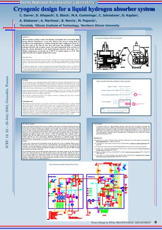
Step IV: Liquid Hydrogen Infrastructure M Hills M Courthold T Bradshaw I Mullacrane P Warburton
LH2 Delivery SystemTechnical Specification • Each system must be capable of filling & emptying a 22L absorber with LH2. • The absorbers utilise thin aluminium windows to minimise multiple scattering. The relatively low burst pressures of these windows require the whole system to operate below 1.5bara. • The absorbers are located within focusing solenoids and form part of the Absorber Focus Coil (AFC) modules; the final system must integrate with these modules. • An alternative substance for ionisation cooling is liquid helium so the system should also be capable of operation at 4.2K.
LH2 Infrastructure in MICE Hall Conceptual layout of the hydrogen system in the MICE Hall • MICE Cooling Channel showing location of AFC modules (image courtesy of S. Yang, Oxford University) High level vents Hydride Bed and Gas Panel Enclosure Location of absorbers in the MICE beamline
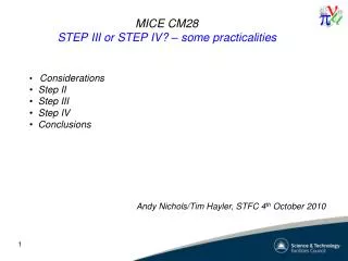
LH2 Delivery System Key Features • The hydrogen will be stored as a metal hydride in a dedicated ‘Hydride Bed’. The bed absorbs hydrogen when cooled below -5°C and evolves gas when heated above 50°C. This has two principle advantages: • Smaller storage volume than gas tanks • Lower risk of explosion, should the tank be damaged, as the gas is trapped in the hydride matrix unless the bed is heated. • The gas is liquefied in the absorber using a closed cycle cryocooler. • The main system components are located in a continuously ventilated enclosure to exhaust any hydrogen leaks to high level vents. Hydrogen system block diagram
Safety Safety relief valvesset to operate at 1.5 bara • The system must comply with DSEAR (the Dangerous Substances and Explosive Atmospheres Regulations) and the controls must comply with the Functional Safety Regulations defined in IEC 61508. • The system is designed to be passively safe: any pressure rise will naturally return gas through relief valves to the hydride bed or, in the case of a rapid rise, to dedicated high level vents.
Ventilation System Risk Assessment - Conclusions • The formation of a flammable atmosphere in the ductwork is considered very unlikely. The only event foreseen during ‘normal’ operation that may release hydrogen into the ductwork is the pumping of residual hydrogen during a purge sequence. This is not planned, but since the properties of the hydride storage bed are not fully tested, it is possible that after returning the hydrogen to the bed, some gas will remain in the pipework. Should this occur, it would be expelled through the vacuum pump exhaust and into the ductwork downstream of the fans.2 Given this situation, and the risk that the pipework may develop a leak, it is not practicable to attempt to eliminate the formation of a flammable atmosphere completely. • Consequently, the Basis of Safety for the system is the elimination of ignition sources. This can be achieved as outlined in above. If all the ventilation system components can be selected to be compliant with ATEX3 (i.e. Equipment and Protective Systems Intended for Use in Potentially Explosive Atmospheres Regulations 1996 (SI 1996/192) for Great Britain), then the risk is significantly reduced. • Any residual risk can be further reduced by controlling access in the vicinity of the system. It is recommended that access to the south wall mezzanine is prohibited during operation of the system. Consideration should also be given to restricting access to outside area around the vent stacks.
R&D Hydrogen System The Hydride Bed (left) and Test Cryostat (right) • An R&D system is being constructed that will demonstrate hydrogen storage, delivery and liquefaction using a test cryostat in place of the final MICE Absorber Focus Coil (AFC) modules. • Assembly and commissioning of the test cryostat with helium took place in December 2009 (see graph showing liquefaction of helium in the test cryostat). • Further testing will be conducted with helium to demonstrate safe operation of the other system components before integration of the hydride bed and testing with hydrogen.
Control Sequences • The system is controlled through a dedicated Programmable Logic Controller (PLC) which operates the control valves, pumps and fans whilst also monitoring temperatures, pressures and levels • Pre-programmed sequences will be used to purge, fill and empty the absorber.
Cryostat Instrumentation Heater on cryocooler Level sensor in absorber pot Cartridge heaters in absorber pot base
Control System PLC Barriers Gas Panel & Cryostat Connectors • Control Panel assembled with (almost) all components needed for He testing • Barriers provide intrinsic safety (<19µJ in the circuit) for all wiring except the heaters. • PLC programmed • Temperature logging • Valve control tested • Example control sequence tested • Heater control implemented
Safety Issues 1 - Cartridge Heaters • “Where terminals of intrinsically safe and non-intrinsically safe circuits are adjacent, their points of connection shall be separated by a distance of 50 mm, or by an insulating barrier or earthed metal barrier which extends to at least the height of the terminals being protected” (IEC79-11 BS 5345 Part 4) • Copper tube used around feedthrough. • Heater feedthrough uses a 12-pin connector; all other connectors are 8-pin, so it is impossible to connect the non-IS circuitry to the thermometer and level sensor circuits.
Safety Issues 2 – Ventilation Fan Sizing • The Gas Panel Enclosure and ventilation system had previously been designated as Zone 2 for purposes of DSEAR regulations • But...is this justified by the level of ventilation available? • Guidance from Baseefa (DSEAR consultants) is that the ‘time of persistence’ of an explosive atmosphere in the event of a leak should be <30mins. • Time of persistence = f(air changes/hour, LEL) • ~90s with fans at full speed • ~7mins with fans on standby • The ‘hypothetical volume’ of the vapour cloud should also be less than the volume of the enclosure. • Hypothetical volume = f(release rate, air changes/hour) • <5m3 (volume of the enclosure) in both cases
Cryostat Thermometry TS05 and TS06 PT1000 and Cernox TS04 – PT1000 TS03 – PT1000
Results from test cryostat commissioning LN2 pre-cool of absorber pot base TS3 (PRT) - absorber TS4 (PRT) – 1st stage cryoheadTS5 (PRT) & TS6 CERNOX) - 2nd stage cryohead
Issues raised during testing • It was estimated that ~6L LHe was produced in the absorber vessel during cryostat testing, which proved that the cryocooler worked at 4.5K, but: • All three level sensor readings varied between ½ to full scale, and oscillated. • It was discovered that the Allen Bradley resistor chains were being energised at 10uA instead of 50-100uA. Increasing the supply current improved stability, but still did not produce believable readings. • The level sensor issue will be investigated further once the system is delivered to RAL, as this was a RAL design.
Continuing work at AS Scientific • Construction of the Gas Panel is underway, now that all components have been delivered, with the exception of the flow meters (on order). • The initial Gas Panel Enclosure design had to be changed, as AS Scientific had located all interface pipe joints outside the enclosure - rectified by moving the joints inside, with gaiters used to seal around pipes, whilst allowing access to joints.
Compatibility with AFC module • Numerous discussions have taken place between all parties to ensure that the control & instrumentation used on the LH2 R&D system is fully compatible with the AFC module and its LH2 Absorber. Very few issues now remain. • It should be noted that the R&D cryostat is sufficiently different to the absorber that comparisons are not meaningful, including the selected cryocooler: • The purpose of the test cryostat is to test the hydrogen delivery system, not to be an accurate thermal analogue of the absorber in the AFC. • We are already using the largest capacity cryocooler, 1.5W at 4K, although the performance of all of these coolers at elevated temperatures is somewhat suspect. • The reason that we need 4K is that we are conducting our preliminary tests with helium. • It is true that we may be better off with a 12K high capacity cooler for LH2, but we would not be able to trial with Helium, which is the important point.
2009/10 Scheduleput virtually on hold since Nov09 Controls development for switch to operation with H2 Acceptance Testing of complete system He R&D Tests