Cryogenic design for a liquid hydrogen absorber system
10 likes | 208 Vues
Legend:. Heat transfer by conduction through the G10 support. Heat transfer by radiation and through MLI. C. Darve 1 , D. Allspach 1 , E. Black 2 , M.A. Cummings 3 , C. Johnstone 1 , D. Kaplan 2 , A. Klebaner 1 , A. Martinez 1 , B. Norris 1 , M. Popovic 1 ,

Cryogenic design for a liquid hydrogen absorber system
E N D
Presentation Transcript
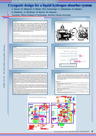
Legend: Heat transfer by conduction through the G10 support Heat transfer by radiation and through MLI C. Darve1, D. Allspach1, E. Black2, M.A. Cummings3, C. Johnstone1, D. Kaplan2, A. Klebaner1, A. Martinez1, B. Norris1, M. Popovic1, 1Fermilab, 2Illinois Institute of Technology, 3Northern Illinois University Cryogenic design for a liquid hydrogen absorber system ABSTRACT Muon ionization-cooling is under investigation at Fermilab and several other High Energy Physics Laboratories. A test area (MuCool Test Area) is being built at Fermilab to run components of a cooling cell together under a high power beam test. The first stage of the MuCool Test Area will ensure the feasibility of a liquid hydrogen absorber and cryogenic system. The main requirement of the system is to keep the density fluctuation in the liquid hydrogen absorber lower than 2.5%. Helium refrigeration can provide up to 500 W of cooling capacity at 14 K. This paper describes the cryogenic design of the system. INTRODUCTION Future Muon Collider and Neutrino Factory will require a cooling system to reduce the muon beam's transverse emittance. The current design uses ionization cooling as the beam passes through number of liquid hydrogen absorbers, alternating with accelerating radio-frequency cavities and embedded within a focusing magnetic lattice [1]. A preliminary feasibility study is conducted at Fermilab with one liquid hydrogen (LH2) absorber at a new MuCool Test Area. The LH2 absorber is inserted in a hydrogen loop and housed in a containment vessel to fit the bore of a 5 T solenoid magnet. The first stage of the MuCool Linac Test Area operation under construction will validate the mechanical and thermal design of the liquid hydrogen absorber system. Conceptual design of the cryo-system Cryo-loop The hydrogen loop consists of the liquid hydrogen absorber, He/H2 heat exchanger, LH2 pump, transfer lines, safety devices and instrumentation. The He/H2 heat exchanger regulates the temperature of the hydrogen system so that the LH2 density fluctuation in the liquid hydrogen absorber remains less than 2.5%. We chose to regulate the LH2 temperature between 17 K and 18 K. A 500 W heater mounted on the outer shell of the heat exchanger is used to balance the heat transfer of the hydrogen system, while keeping a constant helium refrigeration capacity of 30 g/s. During operation the hydrogen is circulated by a mechanical pump at a flow rate up to 550 g/s. This 2 HP LH2 pump was designed and built by Caltech as a spare pump for the SAMPLE experiment [4]. The MuCool Linac Test Area LH2 pump is loaned by the SAMPLE collaboration. The transfer lines connecting the absorber, heat exchanger and pump are equipped with safety devices and relief valves venting outside the experimental hall. Containment vessel The hydrogen cryo-loop is housed in a cryostat and is inserted in the 44 cm diameter bore of a cryogenic solenoid magnet. The LH2 loop is thermally insulated in the vacuum vessel by a thermal shield and G10 supporting system. The thermal shield is actively cooled at liquid nitrogen (LN2) temperature and wrapped with 30 layers of multilayers insulation. The containment vessel windows are shaped like the LH2 absorber windows to minimize multiple scattering. The vacuum vessel volume is 52 times larger than the hydrogen cryo-loop capacity in order to withstand the expansion of the saturated liquid hydrogen. Therefore the vacuum vessel volume, being 1300 liters is distributed around the cryo-loop and through pipe venting outside the experimental hall. A pumping system composed of a roughing pump and a turbo-molecular pump will provide an insulation vacuum of 10-4 Pa. Heat transfer from the ambient to the cryostat Magnet @ 300 K 0 W 0 W Cryostat vacuum vessel @ 300 K 1.5 W (39 W if no MLI) 67 W N2 Cryostat Thermal shield @ 80 K Cooling line 6 W 0.2 W 17 W Absorber @ 17 K Cryostat windows Safety factor =2 0.3 W 47 W General refrigeration system He ICEC 19, 22 – 26 July 2002, Grenoble, France CRYOGENIC DESIGN Design of the liquid hydrogen absorber system is completed with respect to the thermo hydraulic behavior of hydrogen flow, thermal calculations, heat exchanger and safety relief valve calculations. The design is based on the American Society of Mechanical Engineers code (ASME) and the Fermi National Accelerator Laboratory safety recommended requirements for hydrogen. The associated controls and instrumentation are based on the US National Electrical Code (NEC) safety requirements for hydrogen. The use of hydrogen is challenging and implies stringent safety controls. A safety Programmable Logic Controller (PLC) is considered. More than 150 temperature sensors, pressure elements, valves within the cryostat are chosen and installed regarding the safety requirements. Additional requirements are radiation hardness for the instrumentation as well as structures to withstand forces during potential quenches of the magnet. Oxygen deficiency detectors and flammable gas detectors are installed in both the experimental hall and the hydrogen manifold. To satisfy safety requirements for the hydrogen system, the relief valve system is redundant. Relief system is composed of fast acting valves, AGCO type valve and parallel plates. The operating pressure of the hydrogen cryo-loop is 1.2 atm. The hydrogen cryo-loop is set to open at 10 psig (0.17 MPa). The containment vessel (vacuum vessel) is sized for a Maximum Allowable Working Pressure (MAWP) of 25 psig (0.27 MPa). Parallel plates designed at Fermilab will be used. The main limiting factor for the thermo hydraulic hydrogen flow is the density change for the LH2 inside the absorber. For subcooled hydrogen, the allowable density change in the LH2 absorber should be less than +/-2.5 %, which corresponds to a temperature gradient less than 4 K. In order to keep some margin with the hydrogen boiling point, hence large density change, the cryo-loop cryogen will be subcooled. The heat exchanger is designed for 500 W, for a nominal temperature gradient of 1 K at 17 K and for the maximum helium flow available by the cryo-plant being 30 g/s. CONCLUSION A cryogenic design for a liquid hydrogen absorber system has been developed at Fermilab. The requirements are based on ASME code and Fermilab safety requirements and US NEC standards. The cryogenic design is based on its ability to maintain a temperature gradient of 1 K at 17 K and 0.12 MPa within a structurally safe containment vessel. The high-powered beam test at the MuCool Test Area using protons extracted from the Fermilab Linac is scheduled to run in 2005 with cryogenic operations beginning in 2003. REFERENCES 1. Rajendran R. et al, Status of Neutrino Factory and Muon Collider Research and Development and future Plans, FNAL-Pub-02/149-E, Batavia, Illinois, USA (2001) 2. J.G. Weisend II et al, The cryogenic system for the SLAC E158 experiment, Advances in cryogenic Engineering (2001), 47 171-179 3. J.G. Weisend II et al, Safety Aspects Of The E158 Liquid Hydrogen Target System, presented at this conference 4. E.J. Beise et al., A high power liquid hydrogen target for parity violation experiments, Research instruments & methods in physics research (1996), 383-391 5. D. Kaplan et al., Progress in Energy Absorber R&D 2: windows, Particle Accelerator Conference 2001 - Chicago, USA (2001) 3888-3890 6. J. Greenwood et al., Failure Metrology using Projected target Videogrammetry, Proceeding of the Coordinate Measurement Systems Conference 2001, Albuquerque, USA (2001) Flow schematic of the MuCool Test Area