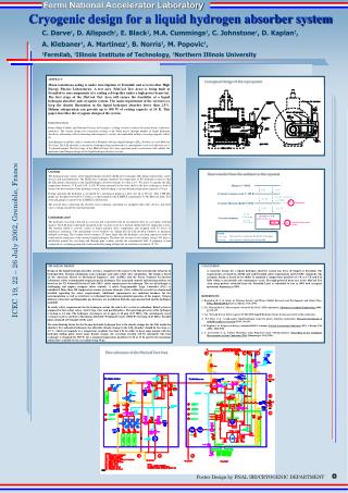
Modular Design for Cryogenic Hydrogen System in MICE
This document outlines the design principles and components of the Modular Integrated Cryogenic Energy (MICE) hydrogen system, focusing on safety and efficiency in neutrino factories. Key features include the decay magnet, various cryogenic modules, and a failsafe design that minimizes hydrogen usage and ensures passive operation. The system incorporates emergency venting solutions, gas storage strategies, and cooling requirements for each module at low temperatures. Discussions include modular staging and alternative hydrogen storage options like metal hydrides, as well as the importance of reducing interactions between absorbers to maintain simplicity.

Modular Design for Cryogenic Hydrogen System in MICE
E N D
Presentation Transcript
MICE Hydrogen System Design Tom Bradshaw Iouri Ivaniouchenkov Elwyn Baynham Columbia Meeting June 2003
MICE Cryogenic Components: • Decay Magnet – part of beam line – early installation and commissioning. Will have its own refrigerator • Implies 9 cryogenic modules: • 3 x Hydrogen absorber and Focusing coil pair • 2 x Spectrometer coils • 2 x Coupling coils • Scintillating fibre detector cryostat
MICE Stages Spring 2006 • Step 1 Decay magnet + Sci-Fi • Step 2 plus spectrometer • Step 3 plus spectrometer • Step 4 plus absorber/focus + hydrogen • Step 5 plus coupling absorber/focus + hydrogen • Step 6 plus coupling absorber/focus + hydrogen 2007 This implies a modular design for the absorber hydrogen system
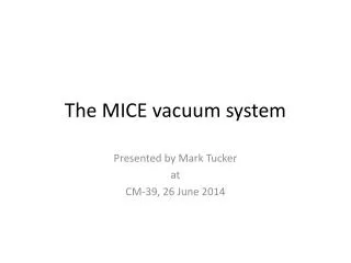
Spectrometer Absorber/Focus Coupling Absorber/Focus Coupling Absorber/Focus Spectrometer Basic Layout Gas Store SciFi Detector Compressors 4K Return 14K 4K Cold box 14K Etc…. Decay Magnet Gate valve Refrigerator Powered valve Relief Valve
Hydrogen Design - Principles • What we are trying to do in the design is: • Make it truly failsafe and passive – no active intervention is required to get the hydrogen out of the system in the event of a problem. • Minimise the amount of hydrogen. • Minimise the volume that has to be considered to be a hydrogen area. • Make it modular to allow for staging. • Minimise interactions between the absorbers to keep the system simple and reduce consequential faults. • Prove we can do it for a neutrino factory
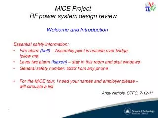
Hydrogen Design - Description Baseline Have gas tanks outside the experimental area piped in – Iouri will show layouts in talk tomorrow. Design is passive. Any emergency relief venting is through evacuated buffer volume – volume of this TBD but may just be a large diameter pipe. Helium purge may be preferable to nitrogen because of sludge and heat capacity issues. Have an igloo around each of the hydrogen modules vented through the roof – layouts TBD because it is complicated by several issues.
P P P P P Vent outside flame arrester Hydrogen tank Volume: 11 m3 Pressure > 0.1 bar H2 Detector H2 Detector H2 Detector P P P VP VP VP VP Hydrogen flow and safety system Version: 09/06/2003 He / N2 Purge system 14 K He from Cold box 18 K He to Compressor via Radiation shield P Fill valve X 2 X 2 H2 Gas bottle 1.7 bar 2.1 bar 12 litre Buffer tank Liquid level gauge Vent valve Vent outside flame arrester Vacuum Ventilation system Internal Window LH2 Absorber 70 K Safety window Vent valve LHe Heat exchanger Vent outside flame arrester Evacuated vent buffer tank Volume: Vacuum vessel Hydrogen module enclosure (igloo) Pressure relief valve Pressure regulator Non-return valve Pressure gauge Vacuum pump Valve Bursting disk
Hydrogen Storage – an Option • Hydrogen storage at STP will require three x 11m3 Vessels • Possibly manageable for MICE but not for a neutrino factory! • Alternative storage solutions being investigated – use of metal hydrides.
Energy research unit at RAL is conducting a small feasibility study Hydrogen storage • Commercially available – designs for automotive and fuel cell use • Absorbtion (exothermic) and release (endothermic) controlled by varying temperature • Large “compression” factor e.g. Ergenics ST-90 (pictured) 61x30x7.6 cm stores 2550 litres in a volume of 13.9 litres factor of 183 JSW Unit Ergenics Unit
Cooling power Requirements Baseline requirement is for : Absorbers 50W per module at 14K (He flow 2.4 g/s ΔT=4K) (MAC Estimate – any advance ?) Focus Coils 4K 14K Leads 5.2W 22W 0.18 g/s From M Greens paper but need new estimates based on current designs – Any thermal models ? In process of clarifying refrigeration requirements so input is needed !