Hydrogen system status
Hydrogen system status. Yury Ivanyushenkov for Elwyn Baynham, Tom Bradshaw, Mike Courthold, Matthew Hills and Tony Jones. Scope. Implementation of R&D system HAZOP recommendations Hydrogen zones classification in MICE hall R&D facility location Hydride bed test by the manufacturer

Hydrogen system status
E N D
Presentation Transcript
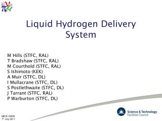
Hydrogen system status Yury Ivanyushenkov for Elwyn Baynham,Tom Bradshaw, Mike Courthold, Matthew Hillsand Tony Jones
Scope • Implementation of R&D system HAZOP recommendations • Hydrogen zones classification in MICE hall • R&D facility location • Hydride bed test by the manufacturer • Hardware procurement • Plans
MICE R&D Hydrogen system HAZOP • R&D Hydrogen delivery system: • Preliminary HAZOP at the Internal Review – November 2005 • Draft response to the Internal Review Panel presented at Osaka CM, 1 March 2006. • Review panel recommended that “A full HAZOP study carried out with the aid of an external specialist, should be completed as a priority”. • R&D system HAZOP study at RAL by SERCO experts – May 2006 MICE Hydrogen system HAZOP
HAZOP: Nodes 1. Metal Hydride Storage Unit (Including Heater/Chiller Unit) 2. Hydrogen Bottle and line to Buffer Volume (Including lines through HA-PV05, HA-RV06 & HA-PV07) 3. Purge/Fill Helium Cylinder and line through HA-PV18 4. Buffer Tank (Including lines through HA-PV08, HA-BD09 & HA-RV10 to Vent) 5. Lines from Buffer Tank to Cryostat 6. Absorber Volume and Condensing Pot 7. Test Cryostat and Mass Spectrometer Port to Vent and exhaust Vent (Including coolant lines) 8. Nitrogen System - Jacket and Ventilation Purge (Including nitrogen cylinder and lines through HA-PV11, HA-BD12 & HA-PV13)) 9. Gas Panel
Hydrogen R&D System: Nodes for HAZOP Node 8 Node 3 Node 1 Node 5 Node 4 Node 7 Node 6 Node 6 Node 9 Node 2
HAZOP Recommendations HAZOP Recommendations Node 1 (Metal Hydride Storage Unit): 1. Look at pressure of hydride bed "on a hot day" i.e. high ambient temperature MC (Failure of heater/chiller pump -> Increase of pressure in system) 2. Consider a chiller pump failure alarm for the hydride bed unit MC (As above) 3. Review consequences of a glycol release (leak) onto plant items from the chiller AJ (Leak in pipework -> Ehylene glycol dripping onto plant/equipment) 4. Review appropriate methods of crane operating areas to reduce risk of damage to plant from impact/dropped loads AJ (Dropped load from crane -> Damage to plant/equipment e.g. ruptured pipework) 5. Consider linking temperature monitor with heater chiller operation to avoid overheating in the event of thermostat failure MC (Failure of thermostat in heating unit -> Temperature >30C causing rise in pressure) 6. Consider automation of hydride bed hand valve MC (As above) 7. Assess ignition sources around the hydrogen generation unit to reduce possibility of fire in the MICE hall CN (External fire in the MICE hall -> Possible flame impingement on metal hydride unit) 8. Review hydride bed operational sequencing for inappropriate actions MC (Failure of thermostat in cooling unit -> Lower temperature)
HAZOP Recommendations (2) Node 2 (Hydrogen Bottle and Line to the Buffer Volume): 9. Review process for filling hydrogen bed for indication that the bed is full (including the location of bottles during storage and filling) MC (Excessive hydrogen delivered to hydride bed -> Higher pressure) 10. Consider back streaming with He during connection to avoid contamination with air during bottle changes MC (Failure to purge hydrogen filling line -> Lower pressure) 11. Review access to roof to avoid exposure to vented hydrogen CN (Emergency venting of hydrogen -> Potential explosive atmosphere at roof level) Node 4 (Buffer Tank): 12. Consider test mechanism to validate (RV10) seal after discharge of cold Hydrogen MC/MH (RV10 operates and discharges cold hydrogen -> Potential to result in failure to reseal) 13. Confirm that control software system conforms with IEC61508 MC (Operator accidentally opens PV08 via control system -> Air ingress to system) Node 5 (Lines from Buffer Tank to Cryostat) 14. Identify appropriate procedure in the event of blockage due to condensation of impurities in buffer tank/cryostat line MC/TB (Condensation of impurities -> Pressure rise in the absorber volume)
HAZOP Recommendations (3) Node 6 (Absorber Volume and Condensing Pot) 15. Ensure hydrogen sensors on UPS in case of loss of power MC (Loss of power -> Inability to monitor state of system) 16. Consider the benefits of having all control system on UPS in the case of loss of power to prove state of system information MC (As above) 17. Ensure that software intervenes when discrepancies are detected with provision for limited operator intervention MC (Operator makes wrong decision -> Cryostat fills with air if, for example, PV25 opened) 18. Consider installation of mass spectrometer (RGA) on PV25 to monitor potential embrittlement issues MC (Hydrogen embrittlement issues -> Leak of hydrogen) 19. Assess ignition sources around the cryostat unit (as for Recommendation 7) CN (External fire on the MICE hall -> Possible flame impingement on cryostat and affect internals)
HAZOP Recommendations (4) Node 7 (Test Cryostat and Mass Spectrometer Port to Vent and Exhaust Vent) 20. Review capability of bursting disc to withstand scenario of RV10 or RV23 pressure surge MH (Activation of RV10 (from buffer volume) or RV23 (hydride bed) -> Disc bursts and hydrogen ingress into cryostat) 21. Confirm whether bursting disc would create ignition source on activation MH (As above) 22. Consider the inclusion of a non-return valve downstream of the burst disc to avoid pressure surge from RV10 or RV23 activation MH (As above) Node 8 (Nitrogen System – Jacket and Vent Purge) 23. Consider installation of flow meter(s) / indication device to alert low/ no flow from nitrogen bottle around nitrogen jacket circuit MH (Empty gas bottle -> Air in ventilation line and cryostat jacket) 24. Consider fitting non-return valve to prevent hydrogen flow into nitrogen system on activation of RV10 or RV23 MH (Discharge through RV10 or RV23 -> Hydrogen into nitrogen line) 25. Review need for protection/location of gas bottles to prevent vehicle (or other) Impacts AJ (Vehicle impact with cylinder bottle storage -> Potential rupture of cylinder) Node 9 (Gas Panel) 26. Review methods to minimise condensation on hydrogen pipework AJ (High moisture content -> Condensation on hydrogen pipework leading to pools of water on floor)
HAZOP recommended Hydrogen R&D System: updated PID
After-HAZOP steps • What’s next : • Final report from Serco received • HAZOP recommendations being examined and implemented • Decide whether another session of HAZOP is required: • - Not for R&D system
Hydrogen Zones in MICE Hall A Safety Officer approach: Follow RAL Safety Code 1(Hydrogen and Deuterium) and BS EN 60079-10 to define hydrogen zones Zones according RAL Safety Code 1: Zone 0 An area or enclosed space within which any flammable or explosive substance, whether gas, vapour, or volatile liquid, is continuously present in concentrations within the lower and upper limits of flammability. Zone 1 An area within which any flammable or explosive substance, whether gas, vapour, or volatile liquid is processed, handled or stored and where during normal operations an explosive or ignitable concentrationis likely to occur in sufficient quantity to produce a hazard. Zone 2 An area within which any flammable or explosive substance whether gas, vapour or volatile liquid, although processed or stored, is so well under conditions of control that the production (or release) of an explosive orignitable concentrationin sufficient quantity to constitute a hazard is only likely under abnormal conditions. Area classification procedureis defined in BS EN 60079-10.The procedure calculates the volume and time of persistence of hydrogen cloud for a given hydrogen release rate and then assigns the zone type (0,1,2 or non-hazardous))
Hydrogen Zones in MICE Hall (2) MICE approach: - the experiment can not afford MICE hall to be Zone 2 -> Engineering of MICE hydrogen system should be done in a way that MICE hall is not Zone 2 ! - Achieved for the hydrogen R&D system (gas panel is under venting hood,jacketing of the test cryostat and of hydrogen lines is implemented) - Can this approach be reliably extended to MICE hydrogen delivery system and AFC modules ?
Hydrogen R&D facility site • Hydrogen R&D facility was originally sited in the MICE hall • Pros: • The R&D system later becomes the first (out of 3) MICE hydrogen system • Cons: • The work on hydrogen R&D interferes with civil work in the MICE hall; • Time schedule is defined by the Phase I preparation time table and puts the hydrogen R&D programme into the background mode ( risk of failure). • That is why it has been suggested to search for a dedicated site for hydrogen R&D facility outside MICE hall. • Pros: • - Eliminates the Cons above, i.e. decouples Phase I programme from the hydrogen R@D programme • Cons: • Will require extra work on new facility layout and new safety case preparation, hence extra cost; • Will later require re-location of hydrogen test system into MICE hall, hence extra cost.
Hydrogen R&D facility site (2) Cryogenics Group Lab MICE Hall
New hydrogen R&D facility: Plan • New Hydrogen R&D facility: • Facility layout • Safety case • -> should get OK by RAL Safety • Detailed layout • Site modification ( build a partition, install venting system, modify electrics etc.) • Hardware installation Note: limited man power -> delays
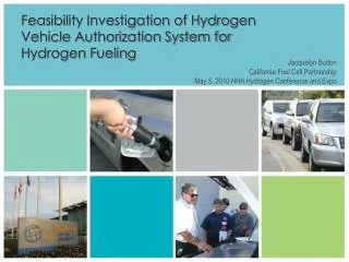
Hydride Bed • Metal hydride storage tank is arrived to RAL. • It has been tested by the manufacturer: • - Hydride bed was initially charged • at 30 bar with 32000 NL of hydrogen; • - then discharged • 30500 NL of hydrogen removed from the tank at a flow rate of 50 NL/min and • at the heating temperature of about 65-70 °C • - and then charged at low pressure • tank filled with 24895 NL of hydrogen at 1.6 bar abs, temperature of about • -10 °C with flow rate of 50 NL/min (-> 24000 NL/8 hours) • Test results: the hydride bed fulfills the spec • Test recommendations for a heater/chiller unit: • Heating/ cooling power ≥ 3kW • Temperature range: -30 °C - +70 °C .
Heating/chilling unit for hydride bed LH50 PRESTO Temperature Control System by JULABO LH50 model – water cooled LH47 model – air cooled (reduced cooling/heating power)
Plans • What’s next : • Assess Cryogenics Group Lab as a Hydrogen R&D facility site • Continue hardware procurement: heating/chilling unit, test cryostat and gas panel • Finish implementations of HAZOP and Internal Review recommendations • Complete response to the Internal Review and submit it to Technical Board