Single Line Tethered Glider
400 likes | 544 Vues
Single Line Tethered Glider. Sub-System Level Design Review. Team P14462. Kyle Ball Matthew Douglas William Charlock. Jon Erbelding Paul Grossi Sajid Subhani. Team Introduction. Agenda. Project Description Review Engineering Requirements Review Functional Decomposition Review

Single Line Tethered Glider
E N D
Presentation Transcript
Single Line Tethered Glider Sub-System Level Design Review Team P14462 Kyle Ball Matthew Douglas William Charlock Jon Erbelding Paul Grossi Sajid Subhani
Agenda • Project Description Review • Engineering Requirements Review • Functional Decomposition Review • Top 3 Concepts from Last Review • Concept Feasibility • Glider Analysis and Feasibility • Base Station Analysis and Feasibility • Project Planning • Work Breakdown Structure
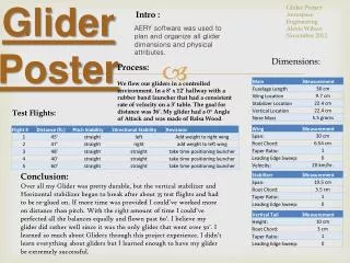
Project Description Review • Goal: Design, build, and test a tethered, small-scale, human-controlled glider. • Critical Project Objectives: • Maintain maximum tension on the tether • Sustaining horizontal and vertical flight paths • Measure and record tether tension and position • Understand the influential parameters for sustained, tethered, unpowered flight Glider Tether Base Station Operator w/ controller
Review of Top 3 System Concepts IMU with Single Axis Load Cell 3 Single Axis Load Cell 2 Potentiometers with Single Axis Load Cell
Choosing the Glider Bixler v1.1 EPO Foam Phoenix 2000 EPO Foam Wing span: 2 [m] Chord length: 0.3 [m] Mass: 0.98 [kg] Front mounted propeller Reinforced • Wing span: 1.4 [m] • Chord length: 0.2 [m] • Mass: 0.65 [kg] • Middle mounted propeller • Only EPO Foam
Choosing the Glider The smaller Bixler glider creates less tension for a larger operating range Able to operate with an affordable load cell
Flight Analysis Wind Speed: ~ 11 mph
Flight Analysis Wind Speed: ~ 22 mph
Flight Analysis Wind Speed: ~ 44 mph
Qualitative DOE • Slower wind speed: lower tension • Larger flight path radius: lower tension • Beta angle peaks: ~ 94-95° • Tension peaks: ~ 20 [m] tether length • Tension must be less than 5000 [N] (1100 lbs)
Quantitative DOE • Choosing flight configuration • Inputs • Maximum allowable tension • Observed wind speed • Outputs • Beta angle • Tether length • Flight path radius
Bridle and Tether Setup Use a tension of 3000 lbs as an overestimate. Maximum allowable stress for Bixler glider: 30 MPa Bridle attached at two points on the fuselage causes structural failure at the wing root with 180 MPa
Ideal Bridle Location Analysis Optimum tether location: 0.51 m from root. Optimum tether angle: 54 deg from airplane
Wing Stress Analysis • Maximum stress: 15 MPa
3 Single-Axis Load Cells Concept 2
CAD Model • Created 3-D model of the system in SolidWorks • Works well when the ball joints are kept in tension as seen in Fig 1. • Ball joints fail when they are put into compression as seen in Fig 2. Fig. 2 Fig. 1
Base Station Equipment Phidgets 3140_0 – S Type Load Cell Bourns 3540S-1-103L Potentiometer
Work Breakdown Structure (10-12) • Paul: • Jon: • Kyle: • Matt: • Saj: • Bill: