Expansion Bus Chapter 6
Expansion Bus Chapter 6. Overview. In this chapter you will learn how to: Identify the structure and function of the expansion bus Identify the modern expansion bus slot Explain classic system resources. Introduction. A slot located inside a computer ( on the motherboard ).


Expansion Bus Chapter 6
E N D
Presentation Transcript
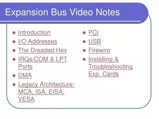
Overview • In this chapter you will learn how to: • Identify the structure and function of the expansion bus • Identify the modern expansion bus slot • Explain classic system resources.
Introduction • A slot located inside a computer (on the motherboard). • Allows additional boards to be connected to it.
Introduction Three points to make a card work successfully in an expansion slot: 1- Physical connection: expansion cards need to be built specifically for the expansion slots (require creation of industry standards) 2- Communication: the card need some way to communicate with CPU (to receive instructions and send data) 3- Drivers: operating system needs some means of enabling users to control the new device
Structure and function of Exp. Bus • Every device in the computer whether soldered to the motherboard or snapped into the sockets or slot are connected to the external data bus and address bus. • Chipset provides extension of address and data buses to the expansion slots, and thus to any expansion cards in those slots. • Bus connect between chipset and slots are called expansion bus • What is system bus?
Structure and function of Exp. Bus • Expansion slot connects to either Northbridge or Southbridge depending on motherboard.
Structure and function of Exp. Bus • Many systems have more than one type of expansion Bus, with slots of one type connecting to Northbridge and slots of another connecting to Southbridge. • AGP slot is always connects to Northbridge.
Expansion Bus speed • All devices solderedto the motherboard run at the speed of the system crystal (system clock). • Ex. a motherboard with a 133-Mhz has at least a 133-Mhz Northbridge chip and at least a 133-Mhz Southbridge. • This doesn’t work for expansion cards: • Cards also must be pushed by clock signal from a crystal. If using system crystal need to make cards for every possible motherboard speed
Expansion Bus speed • IBM had to make an extension to the external data bus to run at it’s own standardized speed • You can use this part of external data bus to snap new devices into PC. • IBM achieved this goal by adding a different crystal, called expansion bus crystal. • No matter how fast the motherboard runs, the expansion slots run at a standard speed. • Expansion bus crystal controls the part of external data bus connected to expansion slots.
All devices soldered to the motherboard run at the speed of the motherboard e.g. 133 Mhz (System crystal) Expansion card run at standard speed. (Expansion crystal)
Expansion Bus speed • Expansion slots run at a much lower speed than frontside bus. The chipset acts as the divider between the two buses, compensating for the speed difference with: • wait states • and special buffering areas.
PC Bus (XT Bus) • On first generation IBM PCs • With 8088 processor with speed of 4.77 MHz • 8-bit wide of external data bus • 7-Mhz speed (of expansion bus) • Manual configuration. What does it means? • In this time expansion bus is faster than CPU speed.
AT Bus • When Intel invented 286 processor, IBM created a new expansion bus that took advantage of 286’s 16-bit external data bus, yet also supported 8-bit cards. • IBM achieved this by simply adding a set of connections to the end of PC bus • Called AT bus • Ran at 7 Mhz • A 16-bit wide • Manual configuration • 8 bit cards could be used in the new 16 bit slots
AT Bus AT Bus XT Bus or PC Bus
Industry Standard Architecture((ISA • Combining knowledge of PC and AT buses leads to creation of a book of standards called the Industry Standard Architecture, or ISA first-generation expansion slots • If a company wanted to build a new kind of adaptor (card) for the PC, they simply followed the specifications in the ISA standard. • ISA bus: • 16-bit wide • 7 Mhz speed • Manual configuration
Modern expansion bus • A better bus to solve problems of old expansion bus was needed • Narrow (Only 16 bits wide) • Slow (Running at only about 7 MHz) • Manually configured by move tiny jumpers (Time consuming) • It must be backward compatible. What doest means? • Several designs to solve the above problems appeared: Micro Channel Architecture (MCA), Extended ISA (EISA), and Video Electronics Standards Association’s VESA, Local Bus (VL-Bus).
Modern expansion bus • They each had shortcoming that made them less than optimal replacements for ISA. • Ex. MCA, EISA was expensive to make. • By 1993, the PC world was eager for a big name to come forward with a fast, wide, easy-to-configure, and cheap new expansion bus (PCI Bus)
PCI Bus • Made by Intel. • PCI (Peripheral Component Interconnect) bus. • It provided a wider, faster, more flexible alternative than any previous expansion bus. • It could coexist with other expansion buses (ex. ISA) to enable users to keep their old ISA cards and slowly migrate to PCI • It had a powerful burst mode feature that enabled very efficientdata transfers • 32-bit wide • 33-Mhz speed • Self-configuring (plug and play - PnP)
PCI Bus PCI card PCI slot
PCI and ISA PCI bus expansion slot are shorter than ISA slot and offset farther from the edge of the system board
Accelerated Graphics Port (AGP) • An AGP slot is a PCI slot but one with a direct connection to the Northbridge. • A specialized video-only version of PCI. • Don’t try to snap a sound card or modem card in to it. • Usually one AGP in Motherboard. Why? • Brown color.
PCI-X • A huge enhancement to current PCI • fully backward compatible (h/w, S/w). • 64-bit wide bus. • much enhanced speed. • Its slots will accept regular PCI cards. • PCI-X 2.0: 4 speed grades (measured in MHz) • PCI-X 66, PCI-X 133, PCI-X 266, and PCI-X 533 . • Its candidate for workstationand serversbecause they have the “need for speed” and the need for “backward compatibility”.
PCI-X and PCI PCI-X PCI
Mini PCI • Mini-PCI is used for laptops
PCI Express (PCI-E) • PCI-E is the latest and the fastest expansion bus, and most popular expansion bus used today. • A PCIe device has its own direct connection to the Northbridge, so it does not wait for other device. • PCIe uses a point-to-point serial connection instead of shared parallel communication used by PCI. • A PCIe connection uses onewire for sending and onefor receiving (instead of using one wire for each bit in PCI parallel communication). • Each of these pairs of wires between a PCIe controller and a device is called a Lane • Each lane allows a maximum transfer rate of 2.5 Gbpsin each direction.
PCI Express PCI-E • PCI Express bus can be built by combining several lanes on order to achieve higher performance . • PCI Express can use 1,2,4,8,12,16 and 32 lanes. to achieve max. bandwidth of 160 Gbps • Most common is 16-lane (x 16) version used for video cards • Other version of PCIe are general purpose (x4).
PCI Express x2 bus • PCI-E with two lanes. • Highly scalable because bandwidth can be increased by increasing the number of lanes.
PCI-E Slots • The PCI Express bus defines a different type of slot based on the number of lanes in the system.
Why Serial Communication ? • Almost all PC buses (ISA, EISA, PCI, AGP) use parallel communication. • Parallel transmits several bits at a time and serial only one bit at a time. For example in a PCI which is parallel 32 bit communication 32 wires carry one bit of data. • Serial communication requires two wires ( one to transmit and another to receive data). • Serial communication allows operations at much higher clock speeds than in parallel because in parallel communication problems with propagation delay appear most frequently . • Parallel communication is half duplex while serial is full duplex.
Full and Half duplex • A half-duplex system provides for communication in both directions, but only one direction at a time (not simultaneously). • Full duplex means, connection that allows communication in two directions simultaneously at once. • Example: • PCI Express can use 1,2,4,8,12,16 and 32 lanes. to achieve max. bandwidth of 160 Gbps • Max bandwidth= (32lanes X 2.5GB)X 2 (Ful duplex)=160 GBPS.
System resources • You can divide communication with CPU into 4 aspects called system resource • System resource are: • I/O address: how CPU sends commands to devices • IRQ: how devices tell CPU they need communication • DMA: how CPU enables devices to talk directly to RAM • Memory: how CPU talks to RAM on devices • Not all devices use all 4 resources: all use #1, most use #2, few use #3 or #4. • New devices must have their system resource configuration. • System resources are now automated
I/O Address • All devices connect to the address and data buses. • Every device in the computer needs an I/O address. • Is different patterns used by the CPU to talk to the devices inside the computer. • All devices respond to unique patterns of ones and zeros built into them. • Most PCs have 65,535 different I/O addresses • (16 bits for I/O address 2^16). • I/O addresses are shown in hexadecimal format from 0000 to FFFF.
Hexadecimal and Binary • Representing tenin binary and hex • Binary 1 0 1 0 (1 eight and 1 two) • Hexadecimal Ah (pronounced “A hex”) Hexadecimal Table 1010 Binary 23 22 21 20 8 4 2 1 1 0 1 0
I/O Address If CPU wants to send I/O address it put the expansion bus into I/O mode through (IO/MEM) wire. When bus goes into I/O mode, all device on bus look for patterns of one and zeroes to appear on the address bus.
Rules of I/O Addresses • All devices must have an I/O address • All devices respond to more than one pattern (I/O address is a range of patterns)- at least four discrete address. • The first value of a range are generally refereed to as base address. • Once a device is using an I/O address no other device can use it (not-shared) • Most I/O addresses were set up by standard IBM. (Example?) • Or can be set at boot by operating system (OS). • Exercise: how do you know I/O addresses for devices of your computer.
Interrupt Requests • CPU can communicateand talkto all device in computer using: • I/O Address bus • BIOS • But how device tell CPU its need attentions: • Interrupt request used by devices to get the CPU’s attention • IRQ0 = System Timer • IRQ1 = Keyboard Controller
Interrupt Requests • Every CPU has an INT (interrupt) wire. • If device puts voltage on this wire. The CPU will: • Stop what it is doing and deal with the interrupting device. • This will be fine if the PC had only one device • But PCs have many device and all of them need to interrupt the CPU. • Therefore PC needs some kind of “traffic cop”.
Interrupt and IOAPIC chip This Traffic cop called IOAPIC • IOAPICchip (I/OAdvanced Programmable Interrupt Controller) chip was hooked to the INT wire and had special interrupt wires called IRQs that run to all devices on the expansion bus.
IRQ (Interrupt ReQuest) • Note: IOAPIC functions are usually built into Southbridge. • Each device that needs to interrupt the CPU activate its IRQ line. • IOAPIC then interrupts CPU • CPU queries IOAPIC to know the device and begins communication with it over the address bus.
IRQ • No two devices could share IRQs • PIC is the previous generation to IOAPIC. • PIC system use fewer IRQs. • PIC had 16 IRQ lines • where as IOAPIC has 24 IRQs lines. • Which IRQ controller do you have in your system? • Some IRQs are not assigned to device we call them “Open IRQs”. • Plug and Play assigns IRQs to new devices as needed
COM and LPT Ports • IBM created standardpreset combinations of IRQs and I/O addresses for serial and parallel ports. • COM port for serial device connections and LPT for parallel device connections. • COM terms came from communication • LPT came from line printer
COM and LPT Ports • Lack of available IRQs in early system lead IBM to double up the IRQ for serial devices. • Exceptionof rule that NO two device could share IRQ. • Combination of I/O address and IRQs:
Direct Memory Access (DMA) • Direct Memory Access (DMA) is the process of Accessing memory directly without involving the CPU in time CPU does internal calculation and address and data bus are available. • It enables the system to run background applications without interrupting the CPU. Example? • Problems: • More than one device wants to use DMA. • CPU suddenly need to use the bus system will another device use it.
DMA: Direct Memory Access • 8237 chip (or DMA controller) controls all DMA functions. • It assigns numbers called DMA channels to enable devices to request use of DMA. • AMD controller also handles the data passes from I/O devices to RAM and vice versa. • DMA chip sends data along the external data bus when • the CPU is busy with internal calculation • and not using the external data bus.