6. Modelling and analysis
570 likes | 779 Vues
6. Modelling and analysis. Josef Machacek Czech Technical University in Prague. Objectives Basic requirements Methods of analysis Influence of deformed geometry Influence of material behaviour Assessment 1 Simple global modelling FE modelling Assessment 2 Examples Conclusions Notes.

6. Modelling and analysis
E N D
Presentation Transcript
6. Modelling and analysis Josef Machacek Czech Technical University in Prague
Objectives Basic requirements Methods of analysis Influence of deformedgeometry Influence of material behaviour Assessment 1 Simple global modelling FE modelling Assessment 2 Examples Conclusions Notes Objectives • This lecture describes principles of modelling and analysis of structures. • Global analyses distinguishing effects of deformed geometry and material non-linearities are presented. • Survey of both simple and FEM analyses and modelling are shown. • Finally some basic examples are presented.
Objectives Basic requirements Methods of analysis Influence of deformed geometry Influence of material behaviour Assessment 1 Simple global modelling FE modelling Assessment 2 Examples Conclusions Notes Outline of the lecture • Basic requirements • Methods of analysis • Influence of deformed geometry • Influence of material behaviour • Simple global modelling of frames, trusses and beams • FE modelling • Examples • Conclusions
Objectives Basic requirements Methods of analysis Influence of deformed geometry Influence of material behaviour Assessment 1 Simple global modelling FE modelling Assessment 2 Examples Conclusions Notes 1. Basic requirements • Calculation model should reflect real global and local behaviour of the designed structure (members, cross sections, joints and placement). • Analysis should correspond to limit states under consideration: ULS (ultimate limit states) or SLS (serviceability limit states), i.e. with appropriate loading, criteria and reliability.
Objectives Basic requirements Methods of analysis Influence of deformed geometry Influence of material behaviour Assessment 1 Simple global modelling FE modelling Assessment 2 Examples Conclusions Notes 1. Basic requirements • Joints are generally modelled (in accordance with EN 1993-1-8) as: • simple (transmitting no bending moments), • continuous (with rigidity and resistance providing full continuityof elements), • semi-continues (in which the joint behaviour needs to be considered in the global analysis). • Ground-structure interaction should be considered in case of significant ground support deformation (see EN 1997).
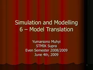
elastic analysis F linear analysis (1st order, elastic) strength plastic analysis collapse fibre plasticity geometrically non-linear (2nd order) δ e e Objectives Basic requirements Methods of analysis Influence of deformed geometry Influence of material behaviour Assessment 1 Simple global modelling FE modelling Assessment 2 Examples Conclusions Notes 2. Methods of analysis Simplified scheme of calculationmodels: Imperfections (global, local), e.g.:
Objectives Basic requirements Methods of analysis Influence of deformed geometry Influence of material behaviour Assessment 1 Simple global modelling FE modelling Assessment 2 Examples Conclusions Notes 2. Methods of analysis General types of analysis: Elastic LA: Linear elastic analysis; LBA: Linear bifurcation analysis; GNA: Geometrically non-linear analysis. Non-Elastic MNA: Materially non-linear analysis; GMNA: Geometrically and materially non-linear analysis; GNIA: Geometrically non-linear analysis elastic with imperfections included; GMNIA: Geometrically and materially non-linear analysis with imperfections included.
Objectives Basic requirements Methods of analysis Influence of deformed geometry Influence of material behaviour Assessment 1 Simple global modelling FE modelling Assessment 2 Examples Conclusions Notes 2. Methods of analysis Simplified GNA (using equilibrium equation on deformed structure but the same “small deflections” as in common LA) is called 2nd order analysis. Such analysis is usually sufficient for investigation of buckling in steel frame structures.
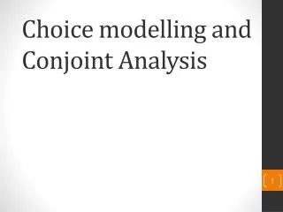
LA F LBA Fcr GNA GNIA e δ Objectives Basic requirements Methods of analysis Influence of deformed geometry Influence of material behaviour Assessment 1 Simple global modelling FE modelling Assessment 2 Examples Conclusions Notes 3. Influence of deformed geometry Simplified scheme of elastic analyses:
Objectives Basic requirements Methods of analysis Influence of deformed geometry Influence of material behaviour Assessment 1 Simple global modelling FE modelling Assessment 2 Examples Conclusions Notes 3. Influence of deformed geometry • LA (1st order analysis): Benefits: Superposition valid, easy. Drawbacks: Approximate solution, necessary toinclude imperfections (global, local)and 2nd order effectsin other ways (by reduction coefficients for buckling).
Objectives Basic requirements Methods of analysis Influence of deformed geometry Influence of material behaviour Assessment 1 Simple global modelling FE modelling Assessment 2 Examples Conclusions Notes 3. Influence of deformed geometry • LBA (linear bifurcation analysis): This analysis uses 2nd order analysis, introducing, however, zero initial imperfections and zero non-axial loading. The resulting critical forces are expressed in the form Ncr,i = cr,iNEd where iЄ(1; ∞) (NEd represent initial set of axial forces) Note: In non-linear bifurcationanalysis the GNIA is used andbifurcation occurs by snap-through of initial imperfection shape.
Objectives Basic requirements Methods of analysis Influence of deformed geometry Influence of material behaviour Assessment 1 Simple global modelling FE modelling Assessment 2 Examples Conclusions Notes 3. Influence of deformed geometry • GNA, GNIA (or 2nd order analysis): Benefits: Direct solution of elastic buckling, covers behaviour of cables. Drawbacks: Superposition can not be used, software necessary.
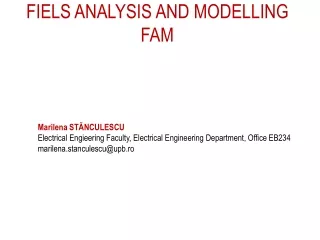
F rigid-plastic analysis elastic-plastic analysis non-linear plastic analysis plastic hinge fibre plasticity Objectives Basic requirements Methods of analysis Influence of deformed geometry Influence of material behaviour Assessment 1 Simple global modelling FE modelling Assessment 2 Examples Conclusions Notes 4. Influence of material behaviour Simplified scheme of plastic analyses:
Objectives Basic requirements Methods of analysis Influence of deformed geometry Influence of material behaviour Assessment 1 Simple global modelling FE modelling Assessment 2 Examples Conclusions Notes 4. Influence of material behaviour • MNA (plastic analysis): Benefits: Higher strength capacity. Drawbacks: May only be used provided that: - steel is sufficiently ductile (fu/fy ≥ 1.1; ≥ 15 %; εu ≥ 15 εy); - for global analysisthecross sections are of class 1; - in global analysis the stability of members at plastic hinges is assured; - software for plastic globalanalysis is desirable.
E/10000 or similar small value (just for numerical reasons) true stress-strain curve stress-strain curve from tests(using original dimension of test coupon) Objectives Basic requirements Methods of analysis Influence of deformed geometry Influence of material behaviour Assessment 1 Simple global modelling FE modelling Assessment 2 Examples Conclusions Notes 4. Influence of material behaviour Modelling of material behaviour: • without hardening • with hardening
Objectives Basic requirements Methods of analysis Influence of deformed geometry Influence of material behaviour Assessment 1 Simple global modelling FE modelling Assessment 2 Examples Conclusions Notes 5. Influence of material behaviour Plastic global analysis models: • non-linear plastic analysis considering the partial plastification of members in plastic zones, • elastic-plastic analysis with plastified sections and/or joints as plastic hinges, • rigid-plastic analysis neglecting the elastic behaviour between hinges.
Objectives Basic requirements Methods of analysis Influence of deformed geometry Influence of material behaviour Assessment 1 Simple global modelling FE modelling Assessment 2 Examples Conclusions Notes Formative Assessment Question 1 • Describe types of analyses. • How 2nd order effects in compression members may be covered? • Describe modelling of material properties. • What are the limits for using an elastic analysis? • What are the prerequisites for using a plastic analysis?
as if with fictitious supports h h Lcr ≤ h Lcr ≤ h Objectives Basic requirements Methods of analysis Influence of deformed geometry Influence of material behaviour Assessment 1 Simple global modelling FE modelling Assessment 2 Examples Conclusions Notes 5. Simple modelling of structures 5.1 Framestability: • First order elastic frames if (using LBA or approx. formula) Critical length is lesser than or equal to system length.
Objectives Basic requirements Methods of analysis Influence of deformed geometry Influence of material behaviour Assessment 1 Simple global modelling FE modelling Assessment 2 Examples Conclusions Notes 5. Simple modelling of structures Note:Instead of using LBA, approximatevalue of cr may be determined from analysis of a compression member with an elastic sway brace: sway buckling mode non-sway bucklingmode (Euler’s critical load) stiffness c < c stiffness c < c L L h For sway buckling mode: Therefore, for sway buckling mode:
Objectives Basic requirements Methods of analysis Influence of deformed geometry Influence of material behaviour Assessment 1 Simple global modelling FE modelling Assessment 2 Examples Conclusions Notes 5. Simple modelling of structures • Second order elastic frames if (using LBA or approx. formula) Three methods of analysis may be used: a) GNIA is generally accepted. If both global and member imperfections are accounted for, no individual stability check for the members is necessary (e.g. compression members are checked for simple resistance to resulting compressionwithout any reduction for buckling).
Objectives Basic requirements Methods of analysis Influence of deformed geometry Influence of material behaviour Assessment 1 Simple global modelling FE modelling Assessment 2 Examples Conclusions Notes 5. Simple modelling of structures b) GNA for global analysis of the structure with global imperfections. Member stability checks should be based on buckling lengths equal to the system lengths. If and sway buckling mode is predominant,as a good approximation an amplified LA may be used (see Eurocode 3, cl. 5.2.2(5B)) where sway effects (i.e. all horizontal loading)should be increased by a multiple Note: For multi-storey frames this simplification can be used provided they are ”regular” (see Eurocode, cl. 5.2.2(6B)
Lcr >h Objectives Basic requirements Methods of analysis Influence of deformed geometry Influence of material behaviour Assessment 1 Simple global modelling FE modelling Assessment 2 Examples Conclusions Notes 5. Simple modelling of structures c) LA for global analysis without considering imperfections. Member stability checks should be based on buckling lengths equal to the global buckling length (received from LBA): or Note: Safe use of this method requires increasing of moments due to sway effects (approx. by 20 %).
Objectives Basic requirements Methods of analysis Influence of deformed geometry Influence of material behaviour Assessment 1 Simple global modelling FE modelling Assessment 2 Examples Conclusions Notes 5. Simple modelling of structures 5.2 Trusses – common LA: • Approximate analysis assuming pin-jointed member ends (secondary moments in members due to stiffness of joints ignored): • Approximate analysis with continuous chords (usual analysis):
H1 H2 e Scheme of truss nodes Objectives Basic requirements Methods of analysis Influence of deformed geometry Influence of material behaviour Assessment 1 Simple global modelling FE modelling Assessment 2 Examples Conclusions Notes 5. Simple modelling of structures • eccentricity of members in nodes should be limited (see EN 1993-1-8, cl. 5.1.5), otherwise eccentricity moments shall be distributed to members. • effects of global and local instabilities in trusses in accordance with cr(global instability is usually negligible, unless slender truss columnis analysed).
Objectives Basic requirements Methods of analysis Influence of deformed geometry Influence of material behaviour Assessment 1 Simple global modelling FE modelling Assessment 2 Examples Conclusions Notes 5. Simple modelling of structures 5.3 Continuous beams (1st class cross-sections, plastic analysis) Methods of elastic-plastic or rigid-plastic analysis (leading to complete, overcomplete or partial kinematic mechanism): - Method of consecutive formation of plastic hinges (used by common software). - Method of virtual works to form kinematic mechanism. - Method of moment redistribution (most common).
number of hinges = number of statically indeterminates + 1 outside spans strengthened inner spans not fully utilized Objectives Basic requirements Methods of analysis Influence of deformed geometry Influence of material behaviour Assessment 1 Simple global modelling FE modelling Assessment 2 Examples Conclusions Notes 5. Simple modelling of structures Examples of beams under uniform loadings: • complete kinematic mechanism • hypercomplete kinematic mechanisms • partial kinematic mechanisms
q elastic moments plastic redistribution Objectives Basic requirements Methods of analysis Influence of deformed geometry Influence of material behaviour Assessment 1 Simple global modelling FE modelling Assessment 2 Examples Conclusions Notes 5. Simple modelling of structures Example: Common analysis of two-span beam under uniform loading(hypercomplete mechanism):
Objectives Basic requirements Methods of analysis Influence of deformed geometry Influence of material behaviour Assessment 1 Simple global modelling FE modelling Assessment 2 Examples Conclusions Notes 6. FE modelling Requirements for FEM are given in EN 1993-1-5, Annex C. Special care is due to: • the modelling of the structural component and its boundary conditions; • the choice of software and documentation; • the use of imperfections; • the modelling of material properties; • the modelling of loads; • the modelling of limit state criteria; • the partial factors to be applied.
Objectives Basic requirements Methods of analysis Influence of deformed geometry Influence of material behaviour Assessment 1 Simple global modelling FE modelling Assessment 2 Examples Conclusions Notes 6. FE modelling Limit state criteria: 1. For structures susceptible to buckling: Attainment of the maximum load. 2. For regions subjected to tensile stresses: Attainment of a limiting value of the principal membrane strain (5%). Other criteria may be used, e.g. attainment of the yielding criterion or limitation of the yielding zone.
Objectives Basic requirements Methods of analysis Influence of deformed geometry Influence of material behaviour Assessment 1 Simple global modelling FE modelling Assessment 2 Examples Conclusions Notes 6. FE modelling The design load magnification factor u (for simplicity a single design load multiplier) to the ultimate limit state should be sufficient to achieve the required reliability: u > 12 where - 1covers the model uncertainty of the FE-modelling used. It should be obtained from evaluations of test calibrations, see Annex D to EN 1990; - 2 covers the scatter of the loading and resistance models. It may be taken as M1 (= 1.0) if instability governs and M2 (= 1.25) if fracture governs.
Objectives Basic requirements Methods of analysis Influence of deformed geometry Influence of material behaviour Assessment 1 Simple global modelling FE modelling Assessment 2 Examples Conclusions Notes Formative Assessment Question 2 • Describe common calculation models for braced building frame. • Describe common calculation models for a truss. • Describe common plastic models for continuous beams under various loadings. • How ULS may be determined when using various FEM models (ranging from LA up to GMNIA)?
Objectives Basic requirements Methods of analysis Influence of deformed geometry Influence of material behaviour Assessment 1 Simple global modelling FE modelling Assessment 2 Examples Conclusions Notes 7. Examples Example 1: Two-bay braced frame Example 2: Two-hinged arch Example 3: Plate under uniform loading
2L 90x8 3 600 2L 90x8 11 400 3 600 2L 110x10 4200 HE 160 B HE 160 B HE 160 B 6 000 6 000 Objectives Basic requirements Methods of analysis Influence of deformed geometry Influence of material behaviour Assessment 1 Simple global modelling FE modelling Assessment 2 Examples Conclusions Notes 7.1 Example 1 Example 1: Two-bay braced frame The frames spaced at distance of 6 m, bracing each 12 m. Geometry and cross sections: composite floor beams:A= 9345 mm2, I = 127.4.106 mm4
153.0 306.0 153.0 30.8 imp 1 137.5 137.5 275.0 56.0 imp 2 137.5 275.0 137.5 62.0 imp 3 HEd,1 HEd,2 HEd,3 VEd,1 VEd,2 VEd,3 Objectives Basic requirements Methods of analysis Influence of deformed geometry Influence of material behaviour Assessment 1 Simple global modelling FE modelling Assessment 2 Examples Conclusions Notes 7.1 Example 1 Loading[kN] • vertical loading of columns; • winter loading due to this bracing; • global imperfections due to this bracing (from 2 cross frames): • imp 1 = 21.6 = 3.2 kN; imp 2 = imp 3 = 21.5 = 3.0 kN.
Objectives Basic requirements Methods of analysis Influence of deformed geometry Influence of material behaviour Assessment 1 Simple global modelling FE modelling Assessment 2 Examples Conclusions Notes 7.1 Example 1 LA - model used model: inappropriate models: unstable long critical lengths of diagonals
Objectives Basic requirements Methods of analysis Influence of deformed geometry Influence of material behaviour Assessment 1 Simple global modelling FE modelling Assessment 2 Examples Conclusions Notes 7.1 Example 1 LA - internal forces (due to loading including global imperfections) -0.46 -0.46 -0.79 -217 -918 -428 -31 -228 MEd [kNm] NEd [kN]
cr,1 = 5.51 cr,2 = 7.37 cr,3 = 8.30 (central column) (bottom diagonal) (middle diagonal) Objectives Basic requirements Methods of analysis Influence of deformed geometry Influence of material behaviour Assessment 1 Simple global modelling FE modelling Assessment 2 Examples Conclusions Notes 7.1 Example 1 LBA – critical modes (loading including global imperfections) 6 first critical modes are shown for demonstration:
Objectives Basic requirements Methods of analysis Influence of deformed geometry Influence of material behaviour Assessment 1 Simple global modelling FE modelling Assessment 2 Examples Conclusions Notes 7.1 Example 1 LBA – critical modes (loading including global imperfections) cr,4 = 11.75 cr,5 = 14.40 cr,6 = 16.95 (right column) (central column) (upper diagonal) Note: The first sway mode is the 15th, where cr,15 = 144.1; Using approximate formula:
Objectives Basic requirements Methods of analysis Influence of deformed geometry Influence of material behaviour Assessment 1 Simple global modelling FE modelling Assessment 2 Examples Conclusions Notes 7.1 Example 1 • Notes for design: - The frame is classified as second order frame (cr,1 = 5.51 < 10). However, the buckling modes are of non-sway character. The possibilities mentioned for analysis (see 5.1) are discussed: a)GNIA may generally be used, where unique imperfectionfor this frame e0 = 8.5 mm was determined in Lecture 5. Approximate global imperfections and imperfections of individual elements in accordance with Eurocode3 or their equivalent transverse loadings may also be used. However, such analyses are generallydemanding.
-0.77 -0.43 -0.44 -217 -918 -428 -31 -228 MEd [kNm] NEd [kN] Objectives Basic requirements Methods of analysis Influence of deformed geometry Influence of material behaviour Assessment 1 Simple global modelling FE modelling Assessment 2 Examples Conclusions Notes 7.1 Example 1 b) GNA for global analysis of the structure with global imperfections is simple, provided non-linear software is available. Resulting internal forces: Compare differences between LA and GNA: here negligible.
Objectives Basic requirements Methods of analysis Influence of deformed geometry Influence of material behaviour Assessment 1 Simple global modelling FE modelling Assessment 2 Examples Conclusions Notes 7.1 Example 1 Member stability checks should be based on buckling lengths equal to the system lengths. Amplified LA is questioned in spite of cr,1 = 5.51 > 3 due to non-sway buckling character. Member stability checks should also be based on buckling lengths equal to the system lengths. Details ofthe method are given for another example inModule 4: Frame Stability.
Objectives Basic requirements Methods of analysis Influence of deformed geometry Influence of material behaviour Assessment 1 Simple global modelling FE modelling Assessment 2 Examples Conclusions Notes 7.1 Example 1 c) LBA gives the first buckling mode which corresponds to buckling of bottom central column, which may be designed for internal forces from LA(imperfection may be neglected) and following global slenderness or global buckling length:
Objectives Basic requirements Methods of analysis Influence of deformed geometry Influence of material behaviour Assessment 1 Simple global modelling FE modelling Assessment 2 Examples Conclusions Notes 7.1 Example 1 The buckling mode is non-sway (see the picture) and due to elastic constraint from upper parts of the columns the Lcr < h = 4200 mm. Note: Other members may be designed conservatively for the same cr,1. Moments due to sway effects (here negligible)should beincreased approx. by 20%.
Objectives Basic requirements Methods of analysis Influence of deformed geometry Influence of material behaviour Assessment 1 Simple global modelling FE modelling Assessment 2 Examples Conclusions Notes 7.1 Example 1 Summary concerning the three approaches: • GNIA introducing all kind of imperfections (suitable for all cr)is demanding, usually not employed. • GNA using global imperfections may be used, followed by member stability checks for system critical lengths. Simplified amplified LA may similarly be used for cr,1 ≥ 3 but is appropriate for predominantly sway buckling modes. • LA followed by member stability checks using critical lengths from LBA should account for moments due to sway effects. • Braced multi-storey frames are usually non-sway.
+ weight of IPE permanent loading 8 m 40 m snow Objectives Basic requirements Methods of analysis Influence of deformed geometry Influence of material behaviour Assessment 1 Simple global modelling FE modelling Assessment 2 Examples Conclusions Notes 7.2 Example 2 Example 2: Two-hinged arch (IPE 360, S355)
Objectives Basic requirements Methods of analysis Influence of deformed geometry Influence of material behaviour Assessment 1 Simple global modelling FE modelling Assessment 2 Examples Conclusions Notes 7.2 Example 2 LA - internal forces:
first critical mode Objectives Basic requirements Methods of analysis Influence of deformed geometry Influence of material behaviour Assessment 1 Simple global modelling FE modelling Assessment 2 Examples Conclusions Notes 7.2 Example 2 LBA - critical loading: (cr = 2.82) When LA is used, the reduction coefficienty(a) = 0.22. e0
Objectives Basic requirements Methods of analysis Influence of deformed geometry Influence of material behaviour Assessment 1 Simple global modelling FE modelling Assessment 2 Examples Conclusions Notes 7.2 Example 2 GNIA - internal forces: Imperfections in first critical mode, in accordance with Eurocode 3, cl. 5.3.2,e0 = 53.3 mm. When GNIA is used, the reduction coefficienty = 1.0.
Objectives Basic requirements Methods of analysis Influence of deformed geometry Influence of material behaviour Assessment 1 Simple global modelling FE modelling Assessment 2 Examples Conclusions Notes 7.2 Example 2 Summary of the comparison of LA andGNIA for the arch: • Using LA the reduction coefficient for compression y(a) = 0.22 shall be used in design. • Using GNIA (geometrically non-linear analysis with imperfections) the maximum moment increased about 1.6 times, while reduction coefficient for compression is y = 1.0. • Comparing resulting cross sections the GNIA is more economic.
Objectives Basic requirements Methods of analysis Influence of deformed geometry Influence of material behaviour Assessment 1 Simple global modelling FE modelling Assessment 2 Examples Conclusions Notes 7.3 Example 3 Example 3: Plate under uniform loading q (edges simply supported with zero membrane stresses)