Download
1 / 50
680 likes | 1.23k Vues
Induction Motor – Vector Control or Field Oriented Control By M.Kaliamoorthy Department of Electrical Engineering. Outline. Introduction Analogy to DC Drive Principles of Field Orientation Control Rotor Flux Orientation Control Indirect Rotor Flux Orientation (IRFO)

E N D
Induction Motor – Vector Control or Field Oriented Control By M.Kaliamoorthy Department of Electrical Engineering
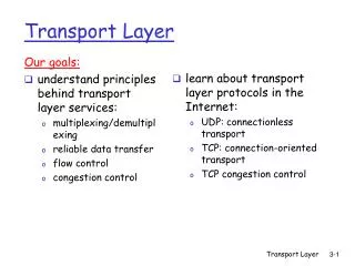
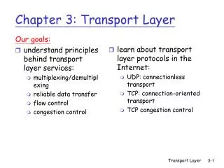
Outline • Introduction • Analogy to DC Drive • Principles of Field Orientation Control • Rotor Flux Orientation Control • Indirect Rotor Flux Orientation (IRFO) • Direct Rotor Flux Orientation (DRFO) • Stator Flux Orientation Control • Direct Stator Flux Orientation (DSFO) • References
Introduction • Induction Motor (IM) drives are replacing DC drives because: • Induction motor is simpler, smaller in size, less maintenance • Less cost • Capability of faster torque response • Capability of faster speed response (due to lower inertia) • DC motor is superior to IM with respect to ease of control • High performance with simple control • Due to decoupling component of torque and flux
Introduction Induction Motor Drive • Scalar Control • Control of current/voltage/frequency magnitude based on steady-state equivalent circuit model • ignores transient conditions • for low performance drives • Simple implementation • Inherent coupling of torque and flux • Both are functions of voltage and frequency • Leads to sluggish response • Easily prone to instability • Vector Control or Field Orientation Control • control of magnitude and phase of currents and voltages based on dynamic model • Capable of observing steady state & transient motor behaviour • for high performance drives • Complex implementation • Decoupling of torque and flux • similar to the DC drive • Suitable for all applications previously covered by DC drives
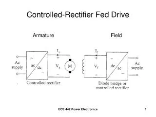
a f Analogy to DC Drive Te = k fIa Te = k fIa = k’ IfIa sin 90 =k’(If x Ia) In the DC motor: fcontrolled by controlling If Ifsame direction as field f Ia same direction as field a Ia and falways perpendicular and decoupled Hence, Keeping f constant, Te controlled by controlling Ia Ia, If , a and f are space vectors
s r a b’ c’ b c Analogy to DC Motor Te = krx s In the Induction Motor: s produced by stator currents r produced by induced rotor currents Both s and r rotates at synchronous speed s Angle between s and rvaries with load, and motor speed r Torque and flux are coupled.
Analogy to DC Motor (1) (2) (3) Induction Motor torque equation : Compared with DC Motor torque equation: Hence, if the angle betweens orr andis is made to be 90, then the IM will behave like a DC motor.
Principles of Field Orientation Control Achieved through orientation (alignment) of rotating dq frame on r or s Stator-Flux Orientation Control Rotor-Flux Orientation Control Hence, if the angle betweens orr andis is made to be 90, then the IM will behave like a DC motor.
qr dr ds ds Principles of Field Orientation Control Rotor-Flux Orientation Control Stator-Flux Orientation Control qs qs qs ds
Principles of Field Orientation Control • Summary of field orientation control on a selected flux vectorf (i.e. either r , s or m):
qr dr ds Rotor Flux Orientation Control qs (4) (5) r (6) • = torque producing current • = field producing current Similar to ia & if in DC motor Decoupled torque and flux control d- axis of dq- rotating frame is aligned with r . Hence, Therefore,
Rotor Flux Orientation Control (7) (8) • From the dynamic model of IM, if dq- frame rotates at general speed g(in terms of vsd, vsq, isd, isq, ird, irq): • r rotates at synchronous speed s • Hence, drqr- frame rotates at s Therefore, g = s • These voltage equations are in terms of isd, isq, ird, irq • Better to have equations in terms of isd, isq, rd, rq
Rotor Flux Orientation Control (9) (10) (11) Rotor flux linkage is given by: From (9): Substituting (8) and (10) into (7) gives the IM voltage equations rotating at s in terms of vsd, vsq, isd, isq, rd, rq:
Rotor Flux Orientation Control (12) (13) (14) Note: Total leakage factor = sl = slip speed (elec.) (15) Important equations for Rotor Flux Orientation Control! Since , hence the equations in rotor flux orientation are:
Rotor Flux Orientation Control (16) (17) (18) (19) Let Using (16), equation (14) can be rearranged to give: is called the “equivalent magnetising current” or “field current” Hence, from (17): where Under steady-state conditions (i.e. constant flux):
qr dr ds Rotor Flux Orientation Control qs (20) r dq- reference frame orientation angle • r rotates at synchronous speed s • drqr- frame also rotates at s • Hence, • For precise control, r must be obtained at every instant in time • Leads to two types of control: • Indirect Rotor Flux Orientation • Direct Rotor Flux Orientation
Indirect Rotor Flux Orientation (IRFO) (21) (22) (23) Orientation angle: Synchronous speed obtained by adding slip speed and electricalrotor speed Slip speed can be obtained from equation (15): Under steady-state conditions ( ):
Indirect Rotor Flux Orientation (IRFO) - implementation (24) (25) • Closed-loop implementation under constant flux condition: • Obtainisdr* fromr*using (16): Obtainisqr* fromouter speed control loop since isqr* Tm* based on (6): Obtain vsdqr* from isdqr* via inner current control loop.
Indirect Rotor Flux Orientation (IRFO) - implementation (26) • Closed-loop implementation under constant flux condition: • Determine the angular position r using (21) and (23): where m is the measured mechanical speed of the motor obtained from a tachogenerator or digital encoder. rto be used in the drqr dsqs conversion of stator voltage (i.e. vsdqr* to vsdqs* concersion).
Rotating frame (drqr) Staionary frame (dsqs) Indirect Rotor Flux Orientation (IRFO) - implementation drqr dsqs transformation 2-phase (dsqs ) to 3-phase (abc) transformation isdr* vsdr* vas* r* vsqs* + Eq. (24) PI PWM VSI vbs* - 2/3 vsqr* ejr isqr* vsds* + + r* vcs* PI PI - - r IRFO Scheme isdr* isqr* slip m r P/2 Eq. (23) + + ias isds isdr NOfield weakening (constant flux) ibs 3/2 e-jr isqs ics isqr
Indirect Rotor Flux Orientation (IRFO) - implementation vsqs* vsdr* ejr vsds* vsqr* isds isdr e-jr isqs isqr • drqr dsqs transformation • dsqs drqr transformation
Indirect Rotor Flux Orientation (IRFO) - implementation vas* vsqs* vbs* 2/3 vsds* vcs* ias isds ibs 3/2 isqs ics 2-phase (dsqs )to 3-phase (abc) transformation: 3-phase (abc) to 2-phase (dsqs ) transform is given by: where: and
Example – IRFO Control of IM An induction motor has the following parameters:
Example – IRFO Control of IM ctd. The motor above operates in the indirect rotor field orientation (IRFO) scheme, with the flux and torque commands equal to the respective rated values, that is r* = 0.7865 Wb and Te* = 183 Nm. At the instant t = 1 s since starting the motor, the rotor has made 8 revolutions. Determine at time t = 1s: • the stator reference currents isd* and isq*in the dq-rotating frame • the slip speed sl of the motor • the orientation angle r of the dq-rotating frame • the stator reference currents isds* and isqs*in the stationary dsqs frame • the three-phase stator reference currents ias*, ibs* and ics*
Example – IRFO Control of IM ctd. Answers:
Indirect Rotor Flux Orientation (IRFO) – field weakening imrd* imrd (rated) r r (base) • Closed-loop implementation under field weakening condition: • Employed for operationsabove base speed • DC motor: flux weakened by reducing field current if • Compared with eq. (17) for IM: • IM: flux weakened by reducing imrd (i.e. “equivalent magnetising current” or “field current)
Rotating frame (drqr) Staionary frame (dsqs) Indirect Rotor Flux Orientation (IRFO) – field weakening implementation With field weakening Same as in slide 20 vsdr* imrd r * vsqs* isdr* + r* + PI PI - - vsqr* isqr* ejr vsds* imrd r + r* + PI PI - - imrdr* r isqr* r slip Eq. (22) + + isds isdr e-jr isqs isqr
Indirect Rotor Flux Orientation (IRFO) – Parameter sensitivity • Mismatch between IRFO Controller and IM may occur • due to parameter changes with operating conditions (eg. increase in temperature, saturation) • Mismatch causes coupling between T and producing components • Consequences: • r deviates from reference value (i.e. r*) • Te deviates in a non-linear relationship from command value (i.e. Te*) • Oscillations occurs in r and Te response during torque transients (settling time of oscillations = r)
Direct Rotor Flux Orientation (DRFO) (27) (28) • Orientation angle: obtained from: • Direct measurements of airgap fluxes mdsand mqs • Estimated from motor’s stator voltages vsdqs and stator currents isdqs Note that:
Direct Rotor Flux Orientation (DRFO) – Direct measurements mds& mqs (29) • Direct measurements of airgap fluxes mdsand mqs • mdsand mqs measured using: • Hall sensors – fragile • flux sensing coils on the stator windings – voltages induced in coils are integrated to obtain mdsand mqs • The rotor flux r is then obtained from: • Disadvantages: sensors are inconvenient and spoil the ruggedness of IM.
Rotating frame (drqr) Stationary frame (dsqs) Direct Rotor Flux Orientation (DRFO) – Direct measurements mds& mqs Flux sensing coils arranged in quadrature isdr* vsdr* vas* r* vsqs* + Eq. (24) PI PWM VSI vbs* - 2/3 vsqr* isqr* ejr vsds* + + r* vcs* PI PI - - r DRFO Scheme mds rds Eq. (29) tan-1 mqs rqs m r P/2 r ias isds isdr NOfield weakening (constant flux) ibs 3/2 e-jr isqs ics isqr
Direct Rotor Flux Orientation (DRFO) – Estimated from vsdqs& isdqs (30) (31) • Estimated from motor’s stator voltages and currents • sdsand sqs obtained from stator voltage equations: • The rotor flux r is then obtained from: • Disadvantages: dc-drift due to noise in electronic circuits employed, incorrect initial values of flux vector components sdq(0)
Direct Rotor Flux Orientation (DRFO) – Estimated from vsdqs& isdqs • Estimated from motor’s stator voltages and currents • This scheme is part of sensorless drive scheme • using machine parameters, voltages and currents to estimate flux and speed • sdqscalculations (eq. 30) depends on Rs • Poor field orientation at low speeds ( < 2 Hz), above 2 Hz, DRFO scheme as good as IRFO • Solution: add boost voltage to vsdqs at low speeds • Disadvantages: Parameter sensitive, dc-drift due to noise in electronic circuits employed, incorrect initial values of flux vector components sdq(0)
Rotating frame (drqr) Stationary frame (dsqs) Direct Rotor Flux Orientation (DRFO) – Estimated from vsdqs& isdqs isdr* vsdr* vas* r* vsqs* + Eq. (24) PI PWM VSI vbs* - 2/3 vsqr* isqr* ejr vsds* + + r* vcs* PI PI - - r DRFO Scheme sds rds vsdqs Eq. (31) Eq. (30) tan-1 isdqs rqs sqs m r P/2 r ias isds isdr NOfield weakening (constant flux) ibs 3/2 e-jr isqs ics isqr
Rotating frame (drqr) Stationary frame (dsqs) Direct Rotor Flux Orientation (DRFO) – field weakening implementation With field weakening Same as in slide 26 or 29 vsdr* imrd r * vsqs* isdr* + r* + PI PI - - vsqr* isqr* ejr vsds* imrd r + r* + PI PI - - r rds tan-1 rqs r r isds isdr e-jr isqs isqr
ds Stator Flux Orientation Control qs (32) qs (33) ds (34) • = torque producing current • = field producing current Similar to ia & if in DC motor Decoupled torque and flux control d- axis of dq- rotating frame is aligned with s. Hence, Therefore,
Stator Flux Orientation Control (7) (8) • From the dynamic model of IM, if dq- frame rotates at general speed g (in terms of vsd, vsq, isd, isq, ird, irq): • s rotates at synchronous speed s • Hence, dsqs- frame rotates at s Therefore, g = s • These voltage equations are in terms of isd, isq, ird, irq • Better to have equations in terms of isd, isq, sd, sq
Stator Flux Orientation Control (35) (36) (37) Stator flux linkage is given by: From (9): Substituting (8) and (36) into (7) gives the IM voltage equations rotating at s in terms of vsd, vsq, isd, isq, sd, sq:
Stator Flux Orientation Control (38) (39) (40) (41) Important equations for Stator Flux Orientation Control! Since , hence the equations in stator flux orientation are:
Stator Flux Orientation Control (42) Varying to control torque causes change in Torque will not react immediately to Equation (40) can be rearranged to give: should be independent of torque producing current From (42), is proportional to and . Coupling exists between and .
Stator Flux Orientation Control – Dynamic Decoupling (43) • De-coupler is required to • overcome the coupling between and (so that has no effect on ) • Provide the reference value for • Rearranging eq. (42) gives: • can be obtained from outer speed control loop • However, eq. (43) requires
Stator Flux Orientation Control – Dynamic Decoupling (44) can be obtained from (41): in (43) and (44) is the reference stator flux vector Hence, equations (43) and (44) provide dynamic decoupling of the flux-producing and torque-producing currents.
Stator Flux Orientation Control – Dynamic Decoupling + s* isds* + isqs* isqs* x from speed controller x sl* Dynamic decoupling system implementation:
ds Stator Flux Orientation Control qs qs ds s dq- reference frame orientation angle • dsqs- frame also rotates at s • For precise control, s must be obtained at every instant in time • Leads to two types of control: • Indirect Stator Flux Orientation • Direct Stator Flux Orientation • s easily estimated from motor’s stator voltages vsdqsand stator currents isdqs • Hence, Indirect Stator Flux Orientation scheme unessential.
Direct Stator Flux Orientation (DSFO) - implementation (45) • Closed-loop implementation: • Obtainisds* fromscontrol loop and dynamic decoupling systemshown in slide 38. Obtainisqs* fromouter speed control loop since isqr* Te* based on (34): Obtain vsdqs* from isdqs* via inner current control loop.
Direct Stator Flux Orientation (DSFO) - implementation (46) (47) (48) • Closed-loop implementation: • Determine the angular position s using: sdsand sqs obtained from stator voltage equations: Note that: Eq. (48) will be used as feedback for the s control loop
Direct Stator Flux Orientation (DSFO) - implementation • Closed-loop implementation: • sto be used in the dsqs dsqs conversion of stator voltage (i.e. vsdqs* to vsdqs* concersion). • sestimated from pure integration of motor’s stator voltages equations eq. (47) which has disadvantages of: • dc-drift due to noise in electronic circuits employed • incorrect initial values of flux vector components sdqs(0) • Solution: A low-pass filter can be used to replace the pure integrator and avoid the problems above.
Rotating frame (dsqs) Stationary frame (dsqs) Direct Stator Flux Orientation (DSFO) - implementation r m P/2 isqs* vsqs* - vas* vsqs* + + r* PI PI PWM VSI vbs* - 2/3 vsds* ejs s* vsds* Decoupling system vcs* PI + s isds* sds vsdqs Eq. (47) + tan-1 isdqs sqs + - s + PI ias isqs isqs - |s| ibs 3/2 e-js Eq. (48) isds ics isds sds sqs
References Trzynadlowski, A. M., Control of Induction Motors, Academic Press, San Diego, 2001. Krishnan, R., Electric Motor Drives: Modeling, Analysis and Control, Prentice-Hall, New Jersey, 2001. Bose, B. K., Modern Power Electronics and AC drives, Prentice-Hall, New Jersey, 2002. Asher, G.M, Vector Control of Induction Motor Course Notes, University of Nottingham, UK, 2002.