Download
1 / 13
130 likes | 245 Vues
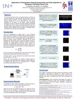
Experimental results of tomographic reconstruction on ONERA laboratory WFAO bench. A. Costille*, C. Petit*, J.-M. Conan*, T. Fusco*, C. Kulcs ár**, H.-F. Raynaud** *ONERA, DOTA – Unité HRA, Châtillon ** L2TI, Université Paris 13, Villetaneuse Anne.costille@onera.fr. Overview. Context

E N D
Experimental results of tomographic reconstruction on ONERA laboratory WFAO bench A. Costille*, C. Petit*, J.-M. Conan*, T. Fusco*, C. Kulcsár**, H.-F. Raynaud** *ONERA, DOTA – Unité HRA, Châtillon ** L2TI, Université Paris 13, Villetaneuse Anne.costille@onera.fr
Overview • Context • WFAO laboratory test bench at ONERA: HOMER • Experimental validation of Wide Field AO (WFAO) concepts in closed-loop • Conclusion and perspectives
I. Context AO is limited by the anisoplanatism effect Development of new WFAO concepts (LTAO and MCAO) and first instruments: Multi-analysis Tomographic reconstruction New control laws Theoretical studies are mature but need for experimental validations Development of a WFAO bench HOMER: Study and comparison of WFAO concept Calibration Field aberrations (WFS and Imaging path) Model identification for control laws implementation Development of new concepts Comparison of control laws Classic control: least-square + integrator LQG control: Estimation and prediction of the turbulent volume, based on a Kalman filter Projection of the estimated turbulence Context - HOMER bench – Experimental results - Conclusion 3
Context - HOMER bench – Experimental results - Conclusion 1. Experimental setup of HOMER bench Wide Field WFS (1002x1004 pixels) ANDOR EMCCD Second DM (88 actuators, ALPAO technology) RTC PC-linux Shaktiware 7x7 microlens array Manufactured at ONERA F = 30mm - dμl = 1.1mm Ground layer DM (52 actuators, ALPAO technology) Visible Imaging camera (1024x1024 pixels) Light source with reconfigurable positions of laser λ = 635 nm Fs < 25 Hz 4
2.Specificities and equations of the system Turbulence Generated by the DMs with turbulent voltages v : φtur = Nturv Where Ntur is the influence matrices of DM52 and DM88, φtur the turbulent phase Turbulence model: AR1 type : vn+1 = Avvn + bv WF Sensing Measurement equation in AO : sn = Dφ + w s: slopes, D: WFS model, φ: measured phase, w: measurement noise Measurement equations for several directions : sn = DMαφ + w Where Mα is the matrix of the projection of the phase in the pupil in directions α On HOMER : one wide field Shack-Hartmann (142x142 pixels / sub-aperture) Context - HOMER bench – Experimental results - Conclusion • 3 WFS on NGS of 16x16 analysis area • Configuration and number of GS modifiable • Correction phase φcor = Nu • Where N is the influence matrices for correction DM (DM52 in LTAO, DM52 + DM88 in MCAO) • u the correction voltages 5
3. Control laws equations Integrator control : least-square reconstructor + integrator Control equation : un+1 = un + G yn = un + g Mcom sn Where g is the integrator gain, Mcom the control matrix : generalized inverse of interaction matrix Mint = DMαN LQG control Where is the estimated phase in Zernike basis Atur is the turbulence transition matrix Hopt is the Kalman Gain P = fct(Mβ,N) the projector of the estimated phase on the DM for correction (β correction directions) Context - HOMER bench – Experimental results - Conclusion 6
3. Control laws equations Integrator control : least-square reconstructor + integrator Control equation : un+1 = un + G yn = un + g Mcom sn Where g is the integrator control, Mcom the control matrix : generalized inverse of interaction matrix Mint = DMαN LQG control in the DM space Where is the estimated voltages Av is the turbulence transition matrix Hopt is the Kalman Gain P = fct(Mβ, D,N) the projector. In MCAO : P = Id Control laws applied with the RTC (Shaktiware) Context - HOMER bench – Experimental results - Conclusion Interaction matrices 7
1. Experimental Conditions Turbulent profile Turbulent layers conjugated with the DMs Cn2 = 50% in each layer D/r0 = 7 (global in the pupil) WFS on 3 NGS in HOMER FoV WFS- Imaging field : 420 x 361 λ/D ( i.e. 81’’x 70,4’’ equivalent 8 m telescope) Representation of anisoplanatism effect for a 8 meter telescope Conservation of the angular separation of the footprint in altitude For D = 8m, FoV = 2’, h = [0,13800]m No correction of the non common path aberrations Impact of the the non common path aberrations : 65% of SR on axis, without turbulence Variation of the SR in the FoV < +/-5 % Context - HOMER bench – Experimental results - Conclusion 8
2. Calibration aspects Context - HOMER bench – Experimental results - Conclusion 1 sub-pupil of HOMER PSFs with astrometry PSFs after correction of astrometry 0.34 1 WFS (real case) 0.34 Position in the FoV (δ) Position in the FoV (δ) 0 0 -0.34 -0.34 -0.34 0 0.34 0 0.34 -0.34 Position dans le champ (δ) Position in the FoV (δ) • Model identification for LQG control in DM space • Models of the DMs, of the WFS, of the projector : calibration of interaction matrices • Model of the turbulence, measurement noise • Relative positions of the WFS in the FoV • Determination of the theoretical positions of the GSs with astrometry • Presence of distortion on the optical path = Deformation of the GS configuration • Errors in astrometry • Errors on the directions of the WFS • Distortion in the optical path • Correction of this distortion by our system not possible • Solution: correction of astrometry to take distortion into account 9
3. Experimental results in WFAO SR open-loop : 7% (average) SR in classic AO On axis : 65% and in the border : 12% (anisoplanatism) SR in MCAO SR closed-loop : 56 % (average in the FoV) Context - HOMER bench – Experimental results - Conclusion No correction AO correction MCAO correction 55% 58% 0.34 65% Position in the FoV (δ) 0 62% -0.34 0 0 0 0.34 0.34 0.34 -0.34 -0.34 -0.34 Position in the FoV (δ) Position in the FoV (δ) Position in the FoV (δ) 10
3. Experimental results in WFAO MCAO results: Slightly better performance with LQG control Mean SR – integrator : 53% - LQG : 56% Turbulence generated by DMs : very favorable for integrator control law Good agreement between numerical and experimental results LTAO results: Test with LQG control Tomographic reconstruction of the turbulence proven (results close to AO case) Test of tomographic reconstruction according to The number of GSs The position of the GSs Context - HOMER bench – Experimental results - Conclusion LTAO 200 55% Position in the FoV (δ) 0 -200 0 200 -200 Position in the FoV (δ) 11
Conclusion HOMER is operational in AO, LTAO and MCAO First experimental validations Of closed-loop LTAO Of LQG control for WFAO systems (LTAO and MCAO) Study of the LQG control in WFAO Gain in performance proven with LQG control Preliminary studies of model identifications issues and impact of model errors Problems of relative positions of WFS in the FoV Distortion effect to take into account (not corrected by the system) Numerical studies on HOMER and VLT case on going Context - HOMER bench – Experimental results - Conclusion 12 12
Perspectives Integration of a turbulent module (summer 2009) Calibration of the turbulence Study of control laws in real conditions and comparison of sub-optimal control laws (POLC…) Problems of model identification with LQG control Choice of the estimation basis Turbulent model Calibration of the models of the system components Calibration issues for WFAO systems: Field aberrations in the imaging path Problems of the relative position of the WFS in the FoV Study of LGS : WFS and control strategy on both LGS and NGS Multi-stage WF sensing (additional WFS after the ground DM52) HOMER web site : http://www.onera.fr/dota/homer Context - HOMER bench – Experimental results - Conclusion 70 % 70 % 70 % 70 % 50 % 60 % 70 % 70 % 13 13