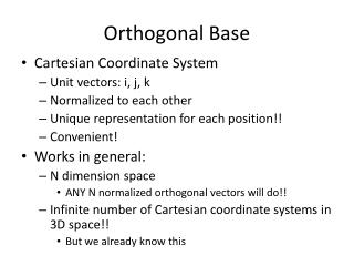
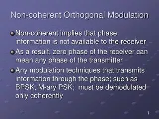
Non-coherent Orthogonal Modulation
Non-coherent Orthogonal Modulation. Non-coherent implies that phase information is not available to the receiver As a result, zero phase of the receiver can mean any phase of the transmitter

Non-coherent Orthogonal Modulation
E N D
Presentation Transcript
Non-coherent Orthogonal Modulation • Non-coherent implies that phase information is not available to the receiver • As a result, zero phase of the receiver can mean any phase of the transmitter • Any modulation techniques that transmits information through the phase; such as BPSK, M-ary PSK; must be demodulated only coherently
sin(2ft) cos(2ft) Transmitter Non-coherent Orthogonal Modulation sin(2ft) cos(2ft) Receiver
Non-coherent Orthogonal Modulation • It is impossible to draw the signal constellation since we do not know where the axes are • However, we can still determine the distance of the each signal constellation from the origin • As a result, the modulation techniques that put information in the amplitude can be detected • FSK uses the amplitude of signals in two different frequencies. Hence non-coherent receivers can be employed to demodulate FSK signals
Non-coherent Orthogonal Modulation • Consider the BFSK system where two frequencies f1 and f2 are used to represented two “1” and “0” • The transmitted signal is given by • If the carrier phase is unknown to the receiver, we can still be able to demodulate the transmitted signal using non coherent demodulation
Non-coherent Orthogonal Modulation • The previous BFSK signal, can be rearranged as shown below • The amplitude (envelope) of the transmitted signal is given by
Non-coherent Orthogonal Modulation • Recall that • The amplitude (envelope) of the received signal is given by
Non-coherent BFSK • There are three common implementations for the equation li • Quadrature receiver using correlator • Quadrature receiver using matched filter • Matched filter using envelope detector
Non-coherent matched filter using envelope detector Since the equation Represent the envelope of the received signal we can demodulate the received signal using an envelope detector as shown in the next slide The envelope detector finds the square root of
Non-coherent matched filter envelope detector An alternate way to show the equivalence between the non-coherent matched filter using envelope detector and the non-coherent detector using quadrature detector is illustrated in mathematically in the next few slides
Noncoherent Orthogonal Modulation • Consider the output of y(t) a filter matched to cos(2fit)
Noncoherent Orthogonal Modulation • The detected envelope at is • Which is exactly the same as in correlator receiver
Generalized binary receiver for noncoherent orthogonal modulation.
Noncoherent Orthogonal Modulation • Decision rule: Let if li> lkfor all k. For examples, decide if l1> l2 • This decision rule suggests that if the envelope (amplitude) of the received signal described in terms of cos(2f1t) is greater than the envelope of the received signal described in terms of cos(2f2t), we say s1(t) was sent
Quadrature receiver equivalent to either one of the two matched filters in part
Noncoherent Orthogonal Modulation • The average probability of error in non-coherent detector can be given by • Where E is the symbol energy and is the power spectral density of the noise
Noncoherent: BFSK • For BFSK, the transmitted symbols are defined by • The receiver can be implemented as shown in the block diagram detailed in the next slide
Non-coherent BFSK, probability of error • Probability of Errors
Differential PSK • Differential PSK is the non coherent version of phase shift keying (PSK) • It eliminates the need for a coherent reference signal by combining two basic operations • Differential encoding of the input binary stream (as explained at the end of Ch. 3) • Applying phase shift keying modulation to the encoded binary data
Differential PSK Differential PSK Instead of finding the phase of the signal on the interval 0<t≤Tb. This receiver determines the phase difference between adjacent time intervals. If “1” is sent, the phase remains unchanged If “0” is sent, the phase changed by 180◦
Differential PSK • Suppose that the transmitted DPSK signal equals to for , where is the bit duration and is the signal energy per bit • Let denote the transmitted DPSK signal for for the case when symbol 1 is being transmitted for the second part of the this time interval • The transmission of symbol 1 leaves the carrier unchanged over the interval • and
Differential PSK • The transmission of symbol 1 leaves the carrier unchanged over the interval , therefore we can define as
Differential PSK Similary we can define for the transmission of symbol 0 for DPSK encoding over the time interval as
Average probability of error of DPSK signals • The average probability of error of DPSK signal is given by • A comparison between the average probability of error of DPSK and non-coherent BFSK shows that the DPSK has a better average probability of error compared with non-coherent BFSK
Generation of DPSK Let the binary sequence represents the binary data to be transmitted using DPSK Let the sequence represents the differentially encoded sequence The encoding rule can be as follows (there is a reference bit as explained in Ch.3)
Generation of DPSK • If the incoming binary symbol is 1, leave the symbol unchanged with respect to the previous bit • If the incoming binary symbol is 0, change the symbol with respect to the previous bit • The differentially encoded sequence is used to phase-shift a carrier with phase angles and representing symbols 1 and 0, respectively
Example of differential encoding process Consider the binary sequence shown below find the differentially encoded sequence and the transmitted phase of the carrier
Generation of DPSK Differential PSK modulator can be realized by the block diagram shown below, where (Xnor operation)
DPSK: Receiver • From the block diagram, we have that the decision rule as • If the phase of signal is unchanged (send “1”) the sign (“+” or “-”) of both xi and xQ should not change. Hence, thel(x) should be positive. • If the phase of signal is unchanged (send “0”) the sign (“+” or “-1”) of both xi and xQ should change. Hence, thel(x) should be negative.
Comparison of digital modulation schemes using a single carrier