Download
1 / 28
280 likes | 436 Vues
Presentation to UAT MOPS WG-5 UAT-WP-7-10. Larry Bachman 240-228-6339 larry.bachman@jhuapl.edu. Core Europe Runs I. Link 16 Baseline, option B No antenna effects Two adjacent channel DMEs 3600 pulse pairs/second for each UAT self-interference Co-site 1030, 1090, DME interference

E N D
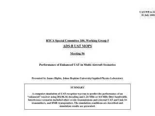
Presentation to UAT MOPS WG-5UAT-WP-7-10 Larry Bachman 240-228-6339 larry.bachman@jhuapl.edu
Core Europe Runs I • Link 16 Baseline, option B • No antenna effects • Two adjacent channel DMEs • 3600 pulse pairs/second for each • UAT self-interference • Co-site 1030, 1090, DME interference • Several altitude options • Highest number of other aircraft in view (usually high altitude (FL300-400) • FL150
Core Europe Runs II • Several transmit power options • Nominal • A3: 50-54 dB • A2: 41-45 dB • A0/A1: 37-41 dB • Option A • A3: 48-52 dB • A2: 42-46 dB • A0/A1: 38.5-42.5 dB • Option B • A3: 50-54 dB • A1/A2: 42-46 dB • A0: 38.5-42.5 dB
Core Europe Runs III • Several receiver configuration options • A2/A3: diversity receivers • A1: switched receiver • A0: bottom antenna only • A0 restrictions • Up to FL150 • Transmits on bottom antenna only • Receive filters • A2/A3 have both 0.8 MHz and 1.2 MHz • A0/A1 have 1.2 MHz only
Differences from Previous Results • Link 16: different baseline scenario • DME • Two adjacent channel DMEs instead of one • Excursion: 3 adjacent channel DMEs • Reduced signal level at top antenna (-10 dB) • Comment: This scenario corresponds to an AWACS transmitting at full capacity over Brussels, flying 1000 ft from the aircraft, which is also near 2-3 high-power DMEs each transmitting at the same frequency within miles of each other.
Order of Results • Comparison of power options • Comparison of receive filter options • Reception by various aircraft types
State Vector Update Times for A3 Receivers at FL 400 with 1.2 MHz Filter
TCP Update Times for A3 Receivers at FL 400 with 1.2 MHz Filter
State Vector Update Times for A3 Receivers at FL 400 with 0.8 MHz Filter
TCP Update Times for A3 Receivers at FL 400 with 0.8 MHz Filter
State Vector Update Times for A3 Receivers at FL 150 with 1.2 MHz Filter
TCP Update Times for A3 Receivers at FL 150 with 1.2 MHz Filter
State Vector Update Times for A3 Receivers at FL 150 with 0.8 MHz Filter
TCP Update Times for A3 Receivers at FL 150 with 0.8 MHz Filter
State Vector Update Times for A1 Receivers at FL 400 with 1.2 MHz Filter
State Vector Update Times for A1 Receivers at FL 150 with 1.2 MHz Filter
State Vector Update Times for A0 Receivers at FL 150 with 1.2 MHz Filter
Maximum Range of MASPS Compliance for SV/TCP Broadcasts from A3 Tx
Maximum Range of MASPS Compliance for SV/TCP Broadcasts from A2 Tx
Maximum Range of MASPS Compliance for SV Broadcasts from A1 Tx
Summary of MASPS Compliance for Power Options for Fully Loaded Simulations • For A3 transmissions, the Nominal and B power options perform equally well in fulfilling MASPS requirements, and power option A performs somewhat worse. • For A2 transmissions, power option A outperforms the other two power options. • For A1 transmissions, power option B outperforms the other two power options.
Comparison of A3 Receiver State Vector Update Times at FL 400 for Two Receive Filters Nominal Power Option used for all Tx
Comparison of A3 Receiver State Vector Update Times at FL 150 for Two Receive Filters Nominal Power Option used for all Tx
Summary of MASPS Compliance for Filter Comparison in Fully Loaded Simulation • For both altitudes considered, A3 compliance with the MASPS requirements was better for the 0.8 MHz filter case. • At FL 150, A2 compliance with the MASPS requirements was better for the 0.8 MHz filter. • A1 was compliant with the MASPS requirements for both filters.
Comparison of State Vector Update Rates for Different Receivers from A3 Transmissions
Comparison of State Vector Update Rates for Different Receivers from A2 Transmissions
Comparison of State Vector Update Rates for Different Receivers from A1 Transmissions
Summary and Conclusions • Power option B was chosen based on subjective judgment of overall compliance with MASPS requirements • The 0.8 MHz filter clearly outperformed the 1.2 MHz filter in A3 receivers for the given interference scenarios • Although the interference environment applied in these simulations was severe, the UAT data link appears capable of fulfilling the MASPS requirements in most situations