John T. Costello
VUV Photoabsorption Imaging. John T. Costello National Centre for Plasma Science & Technology (NCPST) and School of Physical Sciences, Dublin City University www.physics.dcu.ie/~jtc & john.costello@dcu .ie. QuAMP - Open University -September 8th 2003. Outline.

John T. Costello
E N D
Presentation Transcript
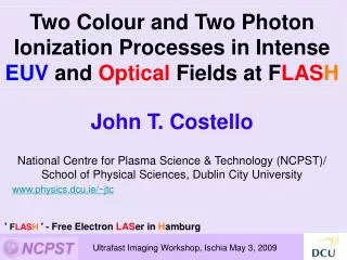
VUV Photoabsorption Imaging John T. Costello National Centre for Plasma Science & Technology (NCPST) and School of Physical Sciences, Dublin City University www.physics.dcu.ie/~jtc & john.costello@dcu.ie QuAMP - Open University -September 8th 2003
Outline 1. ‘Centre for Laser Plasma Research’ /NCPST 2. VUV Photoabsorption/ionization Imaging Principle 3. ‘VPIF’ - VUV Photoabsorption Imaging Facility 4. Charge & State Selected Plasma Specie Images 5. Time Resolved Column Density Maps (Ba+) 6. Conclusions and Current/Proposed Applications
NCPST What is it ? 1. NCPST established with Government/Benefactor funding (Euro 8M) in 1999. Now EU Training Site. 2. Consortium of new and existing laboratories in plasma physics, chemistry and engineering 3. Fundamental and Applied Scientific Goals
The CLPR node comprises 5 (soon to be 6) laboratories focussed on PLD & photoabsorption spectroscopy/ imaging Staff: John T. Costello, Eugene T. Kennedy, Jean-Paul Mosnier and Paul van Kampen PDs: John Hirsch , D Kilbane (post Xmas) PGs: Kevin Kavanangh & Adrian Murphy (JC), Jonathan Mullen (PVK), Alan McKiernan & Mark Stapleton (JPM), Eoin O’Leary & Pat Yeates (ETK) MCFs: Jaoine Burghexta (Navarra) and Nely Paravanova (Sofia) Vacancies: PDRA-1: XUV FEL Experiments (ETK) PDRA-2: Pulsed Laser Deposition (JPM)PhD: Dual Laser Plasma Experiments (PVK/JC)
NCPST/ CLPR - What do we do ? DCU Pico/Nanosecond Laser Plasma Light Sources VUV, XUV & (X-ray) Photoabsorption Spectroscopy VUV Photoabsorpion Imaging VUV LIPS for Analytical Purposes ICCD Imaging and Spectroscopy of PLD Plumes Orsay/Berkeley Synchrotrons Photoion and Photoelectron Spectroscopy Hamburg - FEL Femtosecond IR+XUV Facility Development
How do you make a laser plasma ? Vacuum or Background Gas Target Plasma Assisted Chemistry Laser Pulse- 1 J/ 10 ns Lens Spot Size = 100 mm (typ. Diam.) F > 1011 W.cm-2 Te = 100 eV (~106 K) Ne = 1021 cm-3 Vexpansion 106 cm.s-1 Emitted - Atoms, Ions, Electrons, Clusters, IR - X-ray Radiation
Intense Laser Plasma Interaction S Elizer, “The Interaction of High Power Lasers with Plasmas”, IOP Series in Plasma Physics (2002)
Part II - VUV Photoabsorption Imaging POSTER P45 - Kevin Kavanagh John Hirsch et al, Rev.Sci. Instrum. 74, 2992 (2003)
VUV Photoabsorption Imaging Principle John Hirsch et al, J.Appl.Phys. 88, 4953 (2000) VUV CCD Sample Io(x,y,l,Dt) I(x,y,l,Dt) Pass a collimated VUV beam through the plasma sample and measure the spatial distribution of the absorption.
Laser Plasma VUV/XUV Continua P K Carroll et al., Opt.Lett 2, 72 (1978) E T Kennedy et al., Opt.Eng 33, 3894 (1994)
Motivations 1. To add to the DCU Laboratory a new diagnostic to work alongside the existing spectroscopic systems 2. Pulsed Laser Deposition (PLD) and Dual Laser Plasma (DLP) photoabsortion expeiments require increasingly detailed knowledge of the spatio-temporal characteristics of plasma plumes 3. Lots of photoionization cross sections due (Aarhus/ALS) Limitations of existing imaging methods 1. Direct imaging of light emitted by a plasma using gated array detectors (e.g., ICCD) provides information on excited species only 2. Probing plasma plumes using tuneable lasers provides information on non- emitting species but is limited to wavelengths > 200 nm or so
Why a pulsed,tuneable and collimated beam ? • Pulsed • 1. Automatic time resolution: the VUV pulse ~ laser pulse duration (~15 ns) • 2. By varying the delay between the lasers the plasma can be probed at • different times after its creation • Tuneable • 3. One can access all resonance lines of all atoms and moderately charged • ions with resonances between 30 nm and 100 nm • Collimated • 4. Light path identical for all rays: can derive the eqn of radiative transfer • 5. The detector can be located far away from the sample plasma, reducing • the ‘sample’ plasma signal on the detector, and improving SNR
Q. Anything Else ? A. Yes, it’s a VUV beam 1. VUV light can probe the higher (electron) density regimes not accessible in visible absorption experiments 2. The refraction of the VUV beam in a plasma is reduced compared to visible light with deviation angles scaling as l2 3. The images analysis is not complicated by interference patterns since the VUVcontiuum source has a small coherence length (mms) 4. VUV light can be used to photoionize atoms and ions - this process simplifies greatly the equation of radiative transfer (no bound states). 5. Fluorescence to electron emission branching ratio for many inner shell transitions can be 10-4 or even smaller, almost all photons are converted to electrons
VUV Photoabsorption Imaging Facility- ‘V-P-I-F’
Another one ! VUV Monochromator Mirror Chambers LPLS Chamber Sample Plasma Chamber VUV-CCD
VPIF - Design Considerations & Measured Characteristics
Parameter Focusing Toroid Collimating Toroid Entrance arm 400 mm 400 mm Exit arm 400 mm - Tangential radius 4590 mm 9180 mm Sagittal radius 34.9 mm 63.5 mm Incidence angle 85 degrees 85 degrees Coating Gold Gold Mirror size 60 20 mm 60 20 mm Angle of acceptance 10 10 mrad 10 10 mrad Final Design Parameters
VUV Photoabsorption Imaging Facility- Ray Tracing with ‘Light Path Simulation’ Computed point spread distributions at entrance slit for various apertures.
Ray Tracing with ‘Light Path Simulation’ Beam Footprints Computed and measured VUV beam footprints (A) 0.5m & (B) 1.0 mNOTE LOW DIVERGENCE !!
Spectral Resolution at 54 nm Resolution ‘LPS’ Wavelength (nm) He, 1s - 2p line 50mm/50mm slits R>1000 Iint (Arb. Units) Wavelength (nm)
Spatial Resolution (100mm/100mm slits & l = 50 nm) Vertical Plane (150 mm) Horizontal Plane (120 mm)
VPIF Specifications • Time resolution:~20 ns (200 ps with new EKSPLA) • Inter-plasma delay range:0 - 10 sec • Delay time jitter:± 1ns • Monochromator:Acton™ VM510 (f/12, f=1.0 m) • VUV photon energy range:10 - 35 eV • VUV bandwidth:0.025 eV @25 eV (50mm/50mm slits) • ~0.05 nm @ 50 nm • Detector:Andor™ BN-CCD, • 1024 x 2048/13 m x 13 m pixels • Spatial resolution:~120 m (H) x 150 m (V)
VUV Photoabsorption Imaging Principle VUV CCD Sample Io(x,y,l,Dt) I(x,y,l,Dt) Pass a collimated VUV beam through the plasma sample and measure the spatial distribution of the absorption.
What do we extract from I and Io images ? Absorbance: Equivalent Width: dl
Equivalent Width (nm) 1 - exp[-s(l)NL] = 1 -I/Io = 1 -T Io Wl l
Some Preliminary Results: Time resolved Wl maps of Ca plume species Tune system to 3 unique resonances Ca: 3p64s2 (1S) - 3p54s23d (1P) Ca+: 3p64s (2S) - 3p54s23d (2P) Ca2+: 3p6 (1S) - 3p53d (1P)
Maps of equivalent width of atomic calcium using the 3p-3d resonance at 39.48 nm (31.4 eV)
Maps of equivalent width of singly ionized calcium using the 3p-3d resonance at 37.34 nm (33.2 eV)
Maps of equivalent width of doubly ionized calcium using the 3p-3d resonance at 35.73 nm (34.7 eV)
Plume Expansion Profile of Singly Charged Calcium Ions Plume COG Position (cm) Delay (ns) Ca+ plasma plume velocity experiment: 1.1 x 10⁶ cms-1 simulation: 9 x 10⁵ cms-1 Ba+ plasma plume velocity experiment: 5.7 x 10⁵ cms-1 simulation: 5.4 x 10⁵ cms-1
Extracting maps of column density,e.g.,Barium We measure resonant photoionization, e.g., Ba+(5p66s 2S)+h Ba+*(5p56s6d 2P) Ba2+ (5p61S)+e- h = 26.54 eV (46.7 nm) AND The ABSOLUTE VUV photoionization cross-section for Ba+ has been measured,Lyon et al., J.Phys.B 19, 4137 (1986) Ergo ! We should be able to extract maps of column density - 'NL' = ∫n(l)dl
Maps of equivalent width of singly ionized Barium using the 5p-6d resonance at 46.7 nm
Convert from WE to NL Compute WE for a range of NL and fit a function f(NL) to a plot of NL .vs. WE Apply pixel by pixel dl dl
Result - Column Density [NL] Maps 100 ns 150 ns (C) 200 ns (D) 300 ns (E) 400 ns (F) 500 ns
Summary VPIF - Provides pulsed, collimated and tuneable VUV beam for probing dynamic and static samples Spectral, spatial, divergence etc. all in excellent agreement with ray tracing Recorded time and space resolved maps of equivalent width of Caand Ba plasma species Extracted time and space resolved maps of column density for various time delays Measured plume velocity profiles which compare quite well with simple simulations based on self similar expansion
Current & Future Applications Space Resolved Thin Film VUV Transmission and Reflectance Spectroscopy - PVK ‘Colliding-Plasma’ Plume Imaging Combining ICCD Imaging/Spectroscopy & PI Photoion Spectroscopy of Ion Beams ? Non-Resonant Photoionization Imaging Lots of new measurements from Aarhus & ALS
Collaborators - VPIF Univ. Padua Giorgio Nicolosi Luca Poletto DCU John Hirsch Kevin Kavanagh Eugene Kennedy Collaborators - Proof of Principle @ RAL QUB Ciaran Lewis Andy McPhee R O’Rourke RAL Graeme Hirst Waseem Shaikh DCU John Hirsch et al
Ideally we would like a VUV/ XUV source with lots of photons to do these experiments !!
And there is one in Germany ! (and coming to the UK and US)
X-VUV FELs + Femtosecond OPAs- The Ultimate Photoionization Setup ? • Tuneable: NOW! 80 - 110 nm (20 - 60 nm in 2004) • Ultrafast: 100 fs pulse duration • High PRF: 1 - 10 bunch trains/sec with up to 11315pulses/bunch • Energy: Up to 1 mJ/bunch • Intense: 100 mJ (single pulse) /100 fs /1 mm => 1017 W.cm-2 • Moving to XUV (2005) and X-ray (2010): • Need a Linac + insertion devices => Fraction of a GigaEuro !! • Project Title:‘Pump-Probe’ with DESY-VUV-FEL (EU-RTD) • Aim:FEL + OPA synchronisation with sub ps jitter • URL:http://tesla.desy.de/new_pages/TDR_CD/start.html • Personnel: MBI, DESY, CLPR-DCU, LURE, LLC, BESSY
Femtosecond X-VUV + IR Pump-Probe Facility,Hasylab, DESY DESY, MBI, LURE, BESSY, LLC & NCPST-DCU