Human Gait Analysis using IMU Sensors
Human Gait Analysis using IMU Sensors. Sandeep Kumar, K. Gopinath, Laura Rocchi, Poorna T S Department of Computer Science and Automation Indian Institute of Science, Bangalore, India Dr. Jayanth Sampath, Suyameendra Kulkarni Bangalore Institute of Movement and Research Analysis.

Human Gait Analysis using IMU Sensors
E N D
Presentation Transcript
Human Gait Analysis using IMU Sensors Sandeep Kumar, K. Gopinath, Laura Rocchi, Poorna T S Department of Computer Science and Automation Indian Institute of Science, Bangalore, India Dr. Jayanth Sampath, Suyameendra Kulkarni Bangalore Institute of Movement and Research Analysis. Presented By: Dr. K. Gopinath (Professor, Indian Institute of Science)
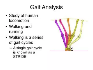
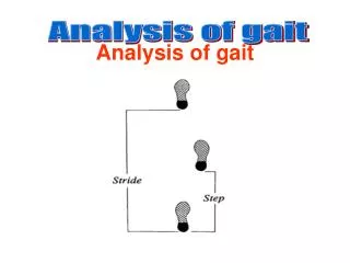
Gait Analysis • Gait Analysis is study of human motion (Walking Style) measuring body movements, body mechanics and the activity of the muscles. • Used to assess, plan, and treat individuals with conditions affecting their ability to walk. Side Plane (Sagittal Plane) Front/Back Plane Top Plane
Different Planes Sagittal Plane: • Plane parallel to side view of the body. • Most of the motions happen in this plane. Frontal/Coronal Plane: • Plane parallel to front view of the body. Transverse Plane: • Plane parallel to the top view of the body.
Current Gold Standard Issues: • Optical System (Camera Based) • Force plates • Body Markers • High Accuracy • Costly • Requirements • Clean room • Lighting condition • Trained physician • Not easy to attach sensors, esp to children
Why IMU Sensors? • Accelerometer, Gyroscope and Magnetometer built into them • Lower cost than an Optical System • Easy to wear • Can be used in any environment EXEL s3 IMU Sensor
AIM Build an end to end “portable” system for Human Gait Analysis to calculate the clinically relevant Gait parameters using optimal number of IMU sensors which can be used in place of Optical Gait Analysis System • Practical approach to calculate clinically relevant Gait parameters using IMU sensors. • Angles calculated in the Sagittal plane within error bounds when compared with the Optical System. • Working prototype for Android System to collect and process the data. Our Contributions:
2 Problems 1: position and angle estimates subject to drift Solution: periodic phases of rest, an even ground, a constant magnetic field, kinematic constraints 2: orientation of the sensor’s coordinate systems with respect to the joint axis or the segments they are mounted on Solution:kinematic constraints with minimization opt. Ref: Joint Axis and Position Estimation from Inertial Measurement Data by Exploiting Kinematic Constraints:Thomas Seel, Thomas Schauer, Jo ̈rg Raisch
Heel Strike and Toe Off • These events marks the start and end of the Gait cycle. • These are one of the most importance gait parameters. • Based on them the final average angle is calculated. We use data from shank and foot sensors to calculate these parameters independently which provides a way to verify the results.
Calculation of angles Knee Flexion Extension The angles can be calculated by integrating the difference of angular velocity (g) around the axis of rotation (j).
Calculation of angles Hip Flexion Extension The angles can be calculated by integrating the difference of angular velocity (g) around the axis of rotation (j).
Calculation of angles Ankle Dorsi-Plantar Flexion The angles can be calculated by integrating the difference of angular velocity (g) around the axis of rotation (j). Note that the order of subtraction is reversed here. It is because of how angles are defined.
Calibration IMU and Optical Data alignment:
Calibration Optimizing Condition: Aim is to find two j vectors, j1 andj2, which correspond to the axis of rotation in the sagittal plane for the two body segments, corresponding to joints, on which sensors are attached. Thigh and Shank for Knee joint, Shank and Foot for ankle joint. g1and g2 are gyroscope readings from sensors on the corresponding joints.
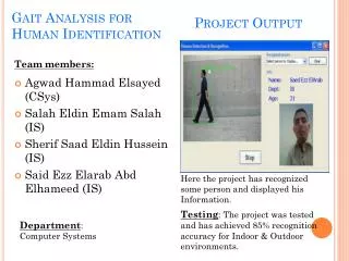
Results: Comparing HT and TO Comparison of HT and TO detection from Shank and Foot sensors. Comparison of HT and TO from Shank and Foot sensors, with optical sensors, independently. Errors within bounds for clinical usage. Sagittal plane angles error in RMSE
Results: Comparing Sagittal Plane Angles Comparison of angles in Sagittal Plane as calculated by IMU sensors vs Optical sensors. Errors within bounds for clinical usage Sagittal plane angles error in RMSE
Other Plane angles: • Angles in Frontal and Transversal • Most of the movements happen in Sagittal plane. • Due to limited movement in these planes, along with noise, makes the angle calculation difficult.
Video: Working of Android Application Calibration Movement. Working of App.
Thank you. Questions ?