Download
1 / 33
330 likes | 524 Vues
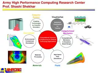
Design of High Availability Systems and Networks Lecture 1 High Availability Computing Basic Issues and Approaches. Prof. Ravi K. Iyer Center for Reliable and High-Performance Computing Department of Electrical and Computer Engineering and Coordinated Science Laboratory

E N D
Design of High Availability Systems and NetworksLecture 1 High Availability ComputingBasic Issues and Approaches Prof. Ravi K. Iyer Center for Reliable and High-Performance Computing Department of Electrical and Computer Engineering and Coordinated Science Laboratory University of Illinois at Urbana-Champaign iyer@crhc.uiuc.edu http://www.crhc.uiuc.edu/DEPEND
Outline • Overview and course objectives • Motivation for high availability design • Taxonomy of dependable computing • Example of a high availability platform
Course Overview • We introduce system view of high availability computing. • We introduce hardware redundancy techniques. • We present capabilities of different error detecting/correcting codes and non-coding detection techniques. • In the context of a high availability platform (Chameleon ARMORs) we illustrate some of these techniques • in providing error detection to DHCP (Dynamic Host Control Protocol) application and MicroLite Controller (MLC) • in designing a failure resilient node/network controller. • We introduce checkpointing and recovery techniques. • We give examples of • a distributed database system, • checkpointing of multithreaded processes: micro-checkpointing and • the IRIX operating system.
Course Overview (cont.) • We describe software fault tolerance techniques including process pairs, robust data structures, recovery blocks and N-version programming. • We give examples of • Tandem on line transaction processing system • high availability design of IBM server • We describe network specific issues for high availability system, including mechanisms /algorithms for providing consistent data and reliable communications in the network; • We present broadcast protocols, agreement protocols, and commit protocols. • In the context of a high availability platform (Chameleon ARMORs) we illustrate some of these techniques in maintaining data consistency in a replicated DHCP server.
Recommended Texts • [Prad96] D.K. Pradhan, ed., Fault Tolerant Computer System Design, Prentice-Hall, 1996 • [John89] B. W. Johnson, Design and Analysis of Fault Tolerant Digital Systems, Addison Wesley, 1989 • [SiSw92] D.P. Siewiorek and R.S. Swarz, Reliable Computer Systems - Design and Evaluation, Digital Press (distributed by Butterworth, 1992, 2nd edition. • [Lyu95a] M.R. Lyu, Handbook of Software Reliability Engineering, McGraw-Hill, 1995 • [Lyu95b] M.R. Lyu, ed., Software Fault Tolerance, J. Wiley & Sons, 1995 • [Birm96] K.P. Birman, Building Secure and Reliable Network Applications, Manning, 1996 • [SiSh94] M. Singhal and N.G. Shivaratri, Advanced Concepts in Operating Systems, McGraw-Hill, 1994
Why Study High Availability Computing!!! • Traditional needs • Long-life applications (e.g., unmanned and manned space missions ) • Life-critical, short-term applications (e.g., aircraft engine control, fly-by-wire) • Defense applications (e.g., aircraft, guidance & control) • Nuclear industry • Newer critical-computation applications • Health industry • Automotive industry • Industrial control systems, production lines • Banking, reservations, switching, commerce
Why Study High Availability Computing!!! (cont.) • Networks • Wired and wireless networked applications • Data mining • Information processing on the Internet (if the Internet becomes the major information highway) • Distributed, networked systems (reliability and security are the major concerns) • intranet - stores, catalog industry (commercial computing) • Scientific computing, education • Typically reliability is not an issue yet. • This might change. In the new 10 Teraflop machine (IBM) reliability is a big concern.
Objectives • System (hardware, software) perspective/view on design issues in high availability computing Applications What can be provided in software and application itself? Application program interface (API) SIFT Middleware How to combine hardware and software fault tolerance techniques - (1) fast error detection in hardware, (2) high efficiency detection and recovery in software How to assess whether the achieved availability meets system requirements What can be provided in the communication layer? Reliable communications What is typically provided in the operating system? Operating system System network What can be provided in COTS hardware to ensure fail-silent behavior of system components (nodes, network)? Hardware Processing elements Memory Storage system
How do We Achieve the Objectives? Applications Checkpointing and rollback, application replication, software, voting (fault masking), Process pairs, robust data structures, recovery blocks, N-version programming, Application program interface (API) SIFT Middleware CRC on messages , acknowledgment, watchdogs, heartbeats, consistency protocols Reliable communications Memory management, detection of process failures, hooks to support software fault tolerance for application Operating system System network Hardware Error correcting codes, N_of_M and standby redundancy , voting, watchdog timers, reliable storage (RAID, mirrored disks) Processing elements Memory Storage system
Based on the temporal persistence Permanent faults,whose presence is continuous and stable. Intermittentfaults, whose presence is only occasional due to unstable hardware or varying hardware and software states (e.g., as a function of load or activity). Transientfaults, resulting from temporary environmental conditions. Based on the origin Physicalfaults, stemming from physical phenomena internal to the system, such as threshold change, shorts, opens, etc., or from external changes, such as environmental, electromagnetic, vibration, etc. Human-made faults, which may be either design faults, introduced during system design, modification, or establishment of operating procedures, or interaction faults, which are violation of operating or maintenance procedures. Fault Classes
Fault Cycle & Dependability Measures Reliability: a measure of the continuous delivery of service; R(t) is the probability that the system survives (does not fail) throughout [0, t]; expected value: MTTF(Mean Time To Failure) Previous repair Fault occurs Maintainability: a measure of the service interruption M(t) is the probability that the system will be repaired within a time less than t; expected value: MTTR (Mean Time To Repair) FAULT Latency Error - fault becomes active (e.g. memory has write 0) MTTF Availability: a measure of the service delivery with respect to the alternation of the delivery and interruptions A(t) is the probability that the system delivers a proper (conforming to specification)service at a given time t. expected value: EA = MTTF / (MTTF + MTTR) ERROR Latency MTBF Error detection (read memory, parity error) REPAIR TIME MTTR Safety: a measure of the time to catastrophic failure S(t) is the probability that no catastrophic failures occur during [0, t]; expected value: MTTCF(Mean Time To Catastrophic Failure) Repair memory Next fault occurs
Faults, Errors, and Failures in Computing Systems Faults Errors Failures Failure to Meet Requirements Reliability, long term - Mission life Reliability, short term - Critical functions - Database protection Availability Detection latencies Containment boundaries Recovery latencies Autonomy Permanent (hard) faults - Natural failures - Natural radiation - HW design errors Transient (soft) faults - Power transients - Switching transients - Natural radiation - Single upsets - Multiple upsets Intermittent faults - Natural failures - Power transients Software faults - SW design errors - System upgrades - Requirements changes External faults Processor
Network Processing Nodes Global Memory Network Operating System Power Supply System I/O Network Interconnect Node Clock Node Interface Network Interface CPUs Cache Memory Processor Modules Local Memory Memory Modules NV Memory Modules Permanent Faults Register File Application Software Software Faults Application Task #1 Transient Faults Instruction Pipeline Software Faults Data Pipeline Node Operating System Intermittent Faults Application Task #N ••• Incorrect Logic Instruction Registers Decoders Program Counter Branch Logic Branch Cache Timing Error Numeric Exception • • • Single Event Upset Switching Transient Power Transient Constraint Error Partial Fault Set for Networked System
s-a-0 Hardware Fault Models Functional level memories, ALUs, network switches Module level decoders, PLA System level processors, links Stack-at Assume lines in gate level circuit stuck at 0 or 1 Faults are located at inputs and outputs of gates Assume basic functionality of gates remains unchanged Example: physical failures in MOS circuits Faulty contact Transistor stuck open or closed Metal lines open Shorts between adjacent metal lines Example: Memories One or more cells arestuck at 0 or 1 One or more cells fail to undergo 0-1 or 1-0 transition Two or more cells arecoupled A 1-0 transition in one cell changes contents in another cell More than one cell isaccessed during READor WRITE A wrong cell is accessedduring READ or WRITE Example: a parallelprocessor topology View machine as agraph - nodes correspond to processors - edges correspond to links Fault Model: A processor (node) orlink (edge) faulty Example: nMOS decoder No output linesactivated An incorrect lineactivated instead of desired line An incorrect lineactivated in additionto desired line
IBM OS Allocation management: Memory region used after deallocation Copying overrun: Program copies data past end of a buffer Pointer management: Variable containing data address corrupted Wrong algorithm: Program works executes but uses wrong algorithm Uninitialized variable: Variable used before initialization Undefined state: System goes into unanticipated state Data error: Program produces or reads wrong data Statement logic: Statements executed in wrong order or omitted Interface error: A module's interface incorrectly defined or incorrectly used Memory leak: Program does not deallocate memory it has allocated Synchronization: Error in locking or synchronization code GUARDIAN 90 Incorrect computation: Arithmetic overflow or an incorrect arithmetic function Data fault: Incorrect constant or variable Data definition fault: Fault in declaring data or data structure Missing operation: Omission of a few lines of source code Side effect of code update: Not all dependencies between software modules considered when updating software Unexpected situation: Not providing routines to handle rare but legitimate operational scenarios Software Fault Models
Software Fault Models (Myrinet Network Switch) Message dropped A message was dropped. Data corrupted A message with incorrect data was sent. Restart The Myrinet Control Program restarted itself. Host interface hung The host interface was not able to operate properly. Host computer crash The host system crashed.
Non-Fault-Tolerant Systems Japan, 1383 organizations (Watanabe 1986, Siewiorek & Swarz 1992) USA, 450 companies (FIND/SVP 1993) Mean time to failure: 6 to 12 weeks Average outage duration after failure: 1 to 4 hours Failure Sources and Frequencies • Fault-Tolerant Systems • Tandem Computers (Gray 1990) • Bell Northern Research (Cramp et al. 1992) • Mean time to failure: • 21 years (Tandem) Failure Sources:
Failure Sources and Frequencies Permanent and Transient Failures • Transient and permanent failures [CMU, Stanford, Illinois] • Ratio of transient failures to permanent failure is 4:1 (80% transient, 20% permanent), varying 8:1 to 2:1. MTBF [h] Tandem GUARDIAN98 98 Tandem NonStop-UX 480 to 2040 Network of 69 SunOS workstations (CRHC) 5
Failure Sources and Frequencies Data Integrity Based on: Illinois, CMU & IBM fault injection experiments • Probability of Detection = 75% (varying from 45% to 85%) • Probability of Correction = 14% (varying from 20% to 10%) • Probability of Corruption = 10% (varying from 35% to 5%) • Overall corruption rate = 132 FITS per microprocessor system (varying from 1531 to 11) • Number of data corruptions in a year per 10,000 systems is 11.6 (varying from 134 to 1) Note: Telecommunication field uses FITS to mean failures/billions hours
Hardware Concurrent Error Detection & Recovery Software Exception Handlers (Instruction Retry) Node Operating System (NOS) Network Management System (NMS) System Manager/ Hardcore Typical Recovery Latencies for a Hierarchical Fault Tolerant Design Recovery Latency 10 s 1 s 100 ms 10 ms 1 ms 100 s 10 s 1 s 100 ns 10 ns 1 ns Recovery Level
Designing for High Availability Objectives & Design Decisions inTandem(TMR) Integrity Design Objectives • Running UNIX applications in a fault tolerant environment without modification to the application software • Continuing to operate in the face of hardware and software faults without loss of performance and compromising data integrity • Providing a high-degree of fault tolerance and data integrity for applications that require very high system availability • no single hardware failure should corrupt the data stored or manipulated in the system • minimized the system outages due to the operating system
Voter Voter TMRC TMRC Global Memory Global Memory IOP IOP Controller Mirrored Disks Controller System Architecture CPU CPU CPU Local Memory Local Memory Local Memory RSB TMRC - Triple Modular Redundant Controller RSB - Reliable System Bus IOP - Input Output Processors RIOB - Reliable I/O Bus RIOB NonStop-V+ Bus1 NonStop-V+ Bus2
Hardware perspective Redundant processors and buses - three identical CPUs and three independent buses Self-checking voters: voting on outputs of the processors (on each I/O operation) Duplicated global memory protected by parity DMA transfer with automatic checksum calculation for data integrity Primary-backup TMR Controller Duplicated heartbeat timer Duplicated I/O controllers Mirrored disks Power supplies with battery backup Software perspective Assertions: assertions (audit routines) are used to determine the validity and consistency of various data structures Assertion-specific forward recovery routines are used to recover from assertion failures Three recovery states:recovery on error detection, execute under probation, and panic on error Subscription based services: an entity in the OS that required notification of an event calls a function to subscribe to the occurrence of that event If that even occurs a function specified by the caller is invoked Nonvolatile memory checksummed by the software Memory scrubbers implemented in OS used to detect and correct latent errors in memory Power on Self Test (POST) to verify the health of the board Reintegration Designing for High Availability Design Decisions inTandem (TMR) Integrity
Hardware & Software Fault Tolerance Interrelationships • Fail-fast hardware (fault intolerant hardware) connected with fault-tolerant software: • The incorrectly functioning module detects the problem and, as quickly as possible, shut itself down. • The operating system identifies the faulty component and takes appropriate recovery actions • Example scenario: • I/O operations are initiated by the OS on behalf of a user. • Data is transferred from CPU to global memory using DMA hardware. • Parity on the bus transfer and the checksum are calculated on the data. • An error is indicated to the processor via a high priority interrupt. • The faulty component is identified by the OS using subscription-based services • The hardware ensures that the OS can continue to operate to recover the system • Appropriate recovery actions are initiated by the OS, e.g., on-line module reintegration.
What Do We Do Next? • To achieve high availability, we need a combination of hardware and software detection and recovery techniques. • How and when the techniques can be use is an art, not a well defined science. • In the following lectures we will: • Gradually introduce and discuss variety of detection and recovery techniques and • Exemplify usage of these techniques by employing them in the Chameleon environment for building highly available distributed application. Chameleon ARMORs Design Requirements • Provide high availability services to the end user: • Applications executed in the network system may require varying levels of availability. • Services must adapt to varying availability requirements. • Provide efficient error detection and fast recovery to minimize system downtime. • Ensure minimum error propagation across the network by • self-checking processes and fail-silent nodes
Programming and Structural Support for Error Detection & Recovery (Chameleon ARMORs Example) • An architecture, mechanisms, and an API to encapsulate detection and recovery techniques that can be efficiently used by applications • A management framework to control the use of these techniques for constructing highly configurable fault tolerance services by providing: • Reusable detection and recovery techniques across different applications • Adaptability to changing availability needs • Scalability and extendability • Fault tolerance services provided through ARMOR (Adaptive Reconfigurable Mobile Objects of Reliability) processes • The ARMOR paradigm provides a foundation for building highly available applications via: • Replaceable basic building blocks - elements • Invocation of elements through operations
ARMOR Process Architecture • Structured way of designing multithreaded object-oriented processes. • Several fault tolerance services can leverage common architecture in all ARMOR processes. • State found in disjoint elements. • Elements subscribe to events; events are delivered as messages are processed. • Common ARMOR infrastructure contains routines to add/remove elements, subscribe to events, deliver events, process messages, etc. ARMOR Infrastructure element element element ARMOR process
Progress Indicator element HB element Checkpoint element Data dependency checking element Text-segment signature element Checksum Element Example ARMOR Configuration Repository of Elements HB element Data dependency checking element ARMOR Interface Progress Indicator element Checksum Element Assertion check element Text-segment signature element Control flow signature element Range-check element ARMOR Checkpoint element
Message 1 OP_1 OP_2 Operations OP_3 : OP_n msg1 msg2 msg3 Message processing threads ARMOR Message Handling • Messages sent from ARMOR to ARMOR. • A message consists of one or more operationsplus payload data • Each incoming message processed by a new ARMOR thread • Message subscription and delivery services in the ARMOR allow for • elements to subscribe to messages that they can process and • the ARMOR interface to deliver operations to elements that have subscribed to a particular operation type • This indirection in ARMOR process is crucial for allowing dynamic reconfiguration
ARMOR-Based Fault Tolerance Services Chameleon Scripting Interface Detection Recovery Fault Masking Using Replication App. Process Crash ExecutionARMOR Errors in memory image of the appl. Text segment signature Control flow errors Signatures- Coarse- grained (I/O)- Fine-grained - Preemptive (PECOS) App. Process Hang Progress indicator Application process restart ARMOR process restart from a checkpoint Tested Configurations - Fault Tolerance Manager (FTM) - DHCP server Process (ARMOR, appl.) Migration (node failure) Node Crash Global HB Livelock ARMOR Process Crash Smart HB (self-adjust time-out + self-test) Daemons, HB ARMOR
Node At the node ARMOR Error Detection & Recovery ARMOR Supported Error Detection and Recovery Detection & RecoveryTechniques ? Layer 1: Process Inside ARMOR process Layer 2: ? Increasing overhead Layer 3: Network Between ARMORs ?