Download
1 / 24
240 likes | 408 Vues
The ATLAS Muon Micromegas R&D project. Konstantinos Nikolopoulos Univ. of Athens / BNL On behalf of the M uon A TLAS M icro M egas A ctivity. 1 st International Conference on Micro Pattern Gas Detectors Kolympari, Greece, 12 -15 June 2009. ATLAS at LHC and the super-LHC scope.

E N D
The ATLAS Muon Micromegas R&D project Konstantinos NikolopoulosUniv. of Athens / BNL On behalf of the Muon ATLAS MicroMegas Activity 1st International Conference on Micro Pattern Gas Detectors Kolympari, Greece, 12 -15 June 2009
ATLAS at LHC and the super-LHC scope General purpose detector : study pp collisions at 14 TeV with a luminosity 1034cm-2s-1→aiming primarily to probe the source of the Electro-Weak Symmetry Breaking Muon SpectrometerAir-core toroids, Precision and Trigger chambersPT resolution:~10% at PT = 1 TeV (standalone)~2.3% at PT = 50 GeV (with InDet) Hadron Calorimetry Fe/Sci + Cu/LArs/E~60%/E3% Inner Detector 2 T solenoid Si Pixels and Strips Transition Radiation Tracker E/M Calorimetry Pb/LAr s/E~10%/E s-LHC to extend life-time of the accelerator, complete LHC’s research program and bridge LHC with future activities (ILC? CLIC?) moderate cost given LHC investmentPossible physics objectives: Higgs rare decays, couplings and Higgs potential,if no Higgs → scattering of W and Zs 2
ATLAS upgrade for the s-LHC • LHC upgrade to happen in two phases • LPhase 1 ~ 3 LLHC (~2014) • LPhase 2 ~ 10 LLHC (s-LHC >2018) • Bunch Crossing = 25 ns / possibly 50 ns (Phase 2) • Muon Spectrometer affected regions : • End-Cap Inner (CSC,MDT,TGC) • End-Cap Middle |η|>2 (MDT,TGC) Total area ~400 m2 Phase I : augment the existing Cathode Strip Chambers Counting rates to be measured with first LHC collisions Reduce uncertainty Average single plane counting rate (Hz/cm2) at the nominal LHC luminosity (CERN-ATL-GEN-2005-001)
Requirements for the Muon System Upgrade To meet goals of s-LHC maintain good detector performance • Operation in a high counting rate environment (>5 kHz/cm2) including dense ionization • High hit reconstruction efficiency(~98%) • High spatial resolution(~100 μm) up tolarge incident angles(<45o) • Good time resolution(~5 ns) to allow bunch crossing identification • Good two-track separation Bulk Micromegas promising technologyfor industrial production of large surface detectors (~1m x 2m) • Cost effective • Mechanically robust Could provide both tracking and trigger Aim : Study whether Micromegas solution suitable for such a large scale muon system
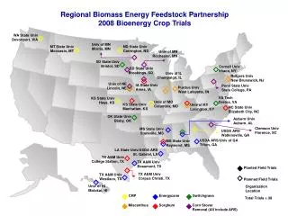
The MAMMA Collaboration Arizona, Athens (U, NTU, Demokritos), Brookhaven, CERN, Harvard, Istanbul (Bogaziçi, Doğuş), Naples, CEA Saclay, Seattle, USTC Hefei, South Carolina, St. Petersburg, Shandong, Stony Brook, Thessaloniki Interest in the project Already 18 collaborating institutesAlso part of RD51 5
The first prototype (P1) Standard bulk Micromegas fabricated at CERN in 2007 • Homogeneous stainless steel mesh • 325 line/inch = 78.2 μm pitch • Wire diameter ~25 μm • Amplification gap ~ 128 μm • 450 mm x 350 mm active area • Different strip patterns 250, 500, 1000, 2000 µm pitch450 mm and 225 mm long • Drift gap : 2-7 mm One of the largest Micromegas available at the time of its production
Read-out Electronics Currently read-out based on ALTRO chip and ALICE DATE system. Operation parameters 32 channels 200 ns integration time 65 charge samples/ch 100 ns/sample 15 pre-samples 1 ADC count ~ 1000 e- No trigger time info recorded Requirements for the final read-out scheme Rate capability ~100 kHz Peaking time in the 20 – 100 ns range Time Resolution ~few nsCharge Measurement Capability (likely 8 – 10 bit ADC)Zero suppression (read-out link bandwidth limitations) Radiation hardness / SEU tolerance
GARFIELD simulation Laboratory tests on P1 with 55Fe Gas gain in the 103-104 region obtained without problems.Measurements in agreement with simulation Electron mesh transparency >95% for field ratio >150
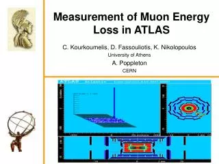
Test Beam : Summer 2008 CERN SPS beam line in 2008 using 120 GeV Pion beam External tracking with three Si detector modules (Bonn Univ.) Three non-flammable gas mixtures with small iso-butane percentage:Ar:CO2:iC4H10 (88:10:2), Ar:CF4:iC4H10 (88:10:2),Ar:CF4:iC4H10 (95:3:2) (“T2K-gas”) Data acquired for different strip patterns and impact angles (0º to 40º)
Event Display Single track event Double track event Si module 1 Si module 3 Si module 6 Micromegas 250 μm strips 500 μm strips
“Geometrical” Efficiency Size of 32 strips connected to r/o ~300 µm diameter 2.54 mm pitch • Ar:CF4:iC4H10 (88:10:2) • Strips: 500 μm pitch • Vmesh = 450 V (35.2 kV/cm) • Drift field = 200 V/cm Black: beam profileRed: tracks w/o Micromegas hit Pillars contribute to the geometrical inefficiency of the chamber at the ~1% level.
Efficiency Vs Amplification • Ar:CF4:iC4H10 (88:10:2) • Vmesh = 470 V (36.7kV/cm) • Drift field = 220 V/cm efficiency > 99% for Gain > 3∙103
Spatial Resolution ~1.2m ~0.5m • Residuals of MM cluster position and extrapolated track from Si. Three contributions to width of distribution : • Si Telescope extrapolation @ μM ~30 μm • Multiple scattering ~53μm • Intrinsic μM resolution ~61 μm Gas: Ar:CF4:iC4H10 (88:10:2) Vmesh = 470 V(36.7kV/cm)Drift field = 220 V/cm Perpendicular tracks σμΜ = (24±7)µm σμΜ = (36±5) µm Strip pitch: 250 µm Strip pitch: 500 µm
Summary of prototype performance The first prototype has been thoroughly tested in the lab and in test beams and it was found to have good performance • Efficiency >99% for Gain >3∙103 • Spatial resolution 24 μm (36 μm) for 250 μm (500 μm) strip width
Simulation of the Micromegas detector Effort to develop a simulation of the full chain from the ionization to the read-out in order to :- Understand performance of chamber in test beam- Study performance of chamber for different parameter choice- Evaluate potential of new ideas
Simulation of the Micromegas detector (II) GARFIELD/HEED/MAGBOLTZ for electron production/drift. Semi-analytical approximation for ion induced charge / include shaper / electronic noise e.t.c Arrival of electrons Drift of ionization electrons from GARFIELD Anode current and shaper output neighbouring strips
Simulation : Residual distribution Simulated residual distribution as a function of strip width for uniform illumination
Comparison with real data The simulated resolution is in agreement with the test beam data resolution
Resolution for Inclined Tracks Spatial resolution for charge interpolation (ratio) and binary read-out as a function of the incidence angle and the strip width.
Ldrift Micromegas as μ-TPC For non-perpendicular incidence position resolution degraded due to fluctuation of charge deposition along the track Use the Micromegas as a μ-TPC Measure arrival time of signals on strips and reconstruct space points in the drift gap Time resolution 1ns σy~ 5-10 μm σx= w/√12~ 70 – 150 μm
Micromegas as μ-TPC Requirements for μ-TPC different wrt charge interpolation techniques.(optimize drift gap/short peaking times/moderate charge measurement) Local track direction can be advantageous for pattern recognition Example test-beam event • Gas: Ar:CF4:iC4H10 (95:3:2) • Drift field = 360 V/cm • Drift velocity = 7.8 cm/µs (Magboltz) • Chamber rotation = (40±3)º • Reconstructed track inclination = (44±4)º 2008 electronics not ideal for this study Try again with better setup Promising/challenging potentially solves angle problem Interesting R&D
The ~½ full size prototype 400mm A half size prototype is almost ready at CERN • 400 x 1300 mm2 active area • “T2K” mesh450 line/inch = 56.4 μm pitch (calendered) 18μm wire diameter • 128 μm amplification gapSegmented • Strip pitch: 250 µm and 500 µm • Long (80 cm) and short (30 cm) strips 1300mm details in Rui de Oliveira’s talk Study performance in lab and in test beam as soon as available The PCB
Future Work Evaluate chamber performance- Half size prototype- μ-TPC methodStudy Spark Protection- Resistive coating (Saclay)- Double stage amplificationBehaviour in s-LHC enviroment- Irradiation test in neutron facility on small chamber -Ageing test (→as soon as materials are defined) See : “Micromegas study for the sLHC enviroment”D. Attie et al. See: “A study of a Micromegas chamber in a neutron beam”G. Fanourakis et al. Define design parameters (chamber+electronics) for phase I upgrade (~ 1m x 1m chamber in CSC region) by end of 2009 Demonstration of suitability for s-LHC LoI (2010)→ Full size prototype (1m x 2m) / production procedures / optimized working points / electronics design
Summary • 350 x 450 mm2 prototype built and tested Good performance in gas amplification and efficiency. Spatial resolution ~ 24 µm (36 µm) with 250 µm (500 µm) strips. • Inclined tracks local track reconstruction possible (µ-TPC) • Simulation study performance dependence on various parameters • 400 x 1300 mm2 prototype almost ready : performance to be studied in 2009. Bulk Micromegas technology is a promising candidate for s-LHC upgrade