Self-Calibrating Audio Signal Equalization
Self-Calibrating Audio Signal Equalization. Greg Burns Wade Lindsey Kevin McLanahan Jack Samet. Project Scope. In any closed room, standing waves exist that change the way audio signals arrive at the ear.


Self-Calibrating Audio Signal Equalization
E N D
Presentation Transcript
Self-Calibrating Audio Signal Equalization Greg Burns Wade Lindsey Kevin McLanahan Jack Samet
Project Scope • In any closed room, standing waves exist that change the way audio signals arrive at the ear. • Variations in amplifier design, speaker efficiency, and room geometry affect the frequency response, degrading it from flat-band operation. • The goal of this project is to automatically calibrate an audio signal to compensate for these effects. Group 15 - Wade Lindsey
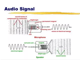
Audio Fundamentals • Pink Noise is a randomly generated signal that exhibits a constant voltage per octave. • A spectrum analyzer can be used to obtain the actual frequency response of an audio signal when placed in a test position in a room. • A graphic equalizer can then be used to adjust the amplifier input to compensate for any deviations off flat-band response Group 15 - Wade Lindsey
Block Diagram Sensor Array PIC Microcontroller Pink Noise Generator MUX Spectrum Analyzer Equalizer Audio Preamp Group 15 - Wade Lindsey
Block Diagram Sensor Array PIC Microcontroller Pink Noise Generator Equalizer MUX Spectrum Analyzer Audio Preamp Group 15 - Wade Lindsey
Equalizer Specifications • 10 Bands (32, 64, 128, 256, 512, 1024, 2048, 4096, 8192, 16384 Hz) • Filters, input, and output constructed using LM351 op-amps • Discrete components and 10kΩ DS1803 digital potentiometers Group 15 - Wade Lindsey
10-Band Equalizer Circuit Group 15 - Wade Lindsey
Built Equalizer Group 15 - Wade Lindsey
Equalizer Response • Frequency response of equalizer with varying resistances tested with HP VEE. Group 15 - Wade Lindsey
Block Diagram Sensor Array PIC Microcontroller Pink Noise Generator MUX Spectrum Analyzer Equalizer Audio Preamp Group 15 - Kevin McLanahan
Block Diagram Sensor Array PIC Microcontroller Pink Noise Generator MUX Spectrum Analyzer Equalizer Audio Preamp Group 15 - Kevin McLanahan
Pink Noise Specifications • Creates pseudorandom digital noise for white noise in first stage at 3dB/dec • Second stage pink noise filter at -3dB/dec • Frequency response 20 Hz – 20 kHz • 33-bit resolution in shift register for pseudorandom number generation • Line level output at 150mV rms Group 15 - Kevin McLanahan
Pink Noise Generation • Equal voltage per octave across audio band. • FFT of Pink Noise viewed on oscilloscope. Group 15 - Kevin McLanahan
Block Diagram Sensor Array PIC Microcontroller Pink Noise Generator MUX Spectrum Analyzer Equalizer Audio Preamp Group 15 - Kevin McLanahan
Block Diagram Sensor Array PIC Microcontroller Pink Noise Generator MUX Spectrum Analyzer Equalizer Audio Preamp Group 15 - Kevin McLanahan
Spectrum Analyzer • Samples input signal from microphone • Performs an FFT (Fast Fourier Transform) algorithm to extract frequency components • Compares relative frequency levels to optimal flat-band response • Samples microphone input at 19.2 μs • Sample length of 256 data points at 8-bit resolution Group 15 - Kevin McLanahan
FFT Explained • Implementing Cooley/Tukey FFT algorithm. • Has Big O of N log N • Takes Fourier matrix of power 2 (28 in our case) • Breaks into 2 log N matrices and performs multiplications on roots of unity (e2πihk/N) • Ultimate result returns a vector with frequency, phase, and magnitude information. Group 15 - Kevin McLanahan
Block Diagram Sensor Array PIC Microcontroller Pink Noise Generator MUX Spectrum Analyzer Equalizer Audio Preamp Group 15 - Greg Burns
Block Diagram Sensor Array PIC Microcontroller Pink Noise Generator MUX Spectrum Analyzer Equalizer Audio Preamp Group 15 - Greg Burns
Microcontroller Software Initialization Mode Sets all initial variables and default settings. Outputs pink noise signal through speakers, receives spectral data from analyzer, and adjusts equalizer to compensate. Calibration Mode Operation Mode Resets MUX to audio source and selects current room location to compensate. Group 15 - Greg Burns
Initialization Mode • Sets system timers and interrupts • Configures input and output pins • Defaults variables to initial conditions • Initializes I2C transfers • Sets digital pots to a predetermined ideal flat-band response Group 15 - Greg Burns
Calibration Mode • Gathers data from spectrum analyzer output • Compares current frequency response peaks to ideal response • Adjusts digital potentiometers based upon previous comparison • Repeats until current frequency response and ideal response fall within 5% tolerance • Calibrates for every room position Group 15 - Greg Burns
Operation Mode • Switches audio source from pink noise to preamp • Sets digital pots to specific values corresponding to room location • Monitors Sensor Arrays for room location variations Group 15 - Greg Burns
Block Diagram Sensor Array PIC Microcontroller Pink Noise Generator MUX Spectrum Analyzer Equalizer Audio Preamp Group 15 - Jack Samet
Future Improvements • Increased number of frequency bands on EQ • Use of DSP processor for improved FFT performance • Use of audio-grade tolerance components • Allow for wide variety of sensor array configurations Group 15 - Jack Samet
Conclusions • Economically feasible and marketable • Modular design allows for easy implementation, innovation, and reproduction • Compatible with most modern stereo systems • Overall a universally usable product from personal to commercial applications Group 15 - Jack Samet
Questions? Group 15
Fin Group 15


![[Advanced] Speech & Audio Signal Processing](https://cdn2.slideserve.com/3915760/advanced-speech-audio-signal-processing-dt.jpg)