Optimizing Radio Environment: Path Loss, Shadow Fading, Multipath, Interference
Explore factors impacting radio communication, including path loss limitations, shadow fading effects, and multipath interference. Understand implications for signal coverage, bit rate, and power efficiency in radio environments.

Optimizing Radio Environment: Path Loss, Shadow Fading, Multipath, Interference
E N D
Presentation Transcript
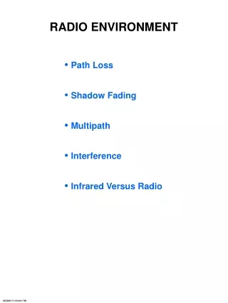
• Path Loss • Shadow Fading • Multipath • Interference • Infrared Versus Radio RADIO ENVIRONMENT 8C32810.71-Cimini-7/98
•Path Loss Limit the Bit Rate • Shadow Fading and/or Coverage • Multipath RADIO ENVIRONMENT 8C32810.83-Cimini-7/98
The path loss exponent a = 2 in free space; 2 £a£4 in typical environments. PATH LOSS MODEL • Different, often complicated, models are used for different environments. • A simple model for path loss, L, is Pr 1 Pt f2da = K L = where Pr is the local mean received signal power, Pt is the transmitted power, d is the transmitter-receiver distance, f is frequency, and K is a transmission constant. 7C29822.011-Cimini-9/97
Pr KPt1 SNR = = • Pn da NoB KPt KPt 1/a ( ) B £ or d £ daNoSNRo NoBSNRo PATH LOSS LIMITATIONS • The received signal-to-noise power ratio, SNR, is where No is the one-sided noise power spectral density and B is the signal bandwidth. • Given the performance requirement SNR ³ SNRo, the path loss imposes limits on the bit rate and the signal coverage. 8C32810.12-Cimini-7/98
• The received signal is shadowed by obstructions such as hills and buildings. • This results in variations in the local mean received signal power, Pr (dB) = Pr (dB) + Gs 2 where Gs ~ N(0, ss ), 4 £ss£ 10 dB. SHADOW FADING • Implications –nonuniform coverage – increases the required transmit power 8C32810.84-Cimini-7/98
• For a desired received power Pr0 the coverage area C defines the percentage of the cell with received power P ³ Pr0. P = Pr0 R ss 4 8 12 a 2 77% 67% 63% 4 85% 77% 71% 6 90% 83% 77% COVERAGE AREA For P(R) = Pr0 C = [1 + exp ( )(1 - erf ( ))], b = 1 1 1 10a log e 2 b2 b ss 2 7C29822.66-Cimini-9/97
Received Power t Delay Spread S h(t) = aiejqid(t-ti) i • Constructive and Destructive Interference of Arriving Rays 10 0 dB With Respect -10 to RMS Value -20 -30 0.5l 0 0.5 1 1.5 t, in seconds 0 10 20 30 x, in wavelength MULTIPATH 8C32810.85-Cimini-7/98
• The delay spread is small compared to the symbol period. • The received signal envelope, r, follows a Rayleigh or Rician distribution. Pr (dB) = Pr (dB) + Gs + 20 log r Received Signal Power (dB) path loss shadow fading Rayleigh fading log (distance) • Implications – increases the required transmit power – causes bursts of errors FLAT FADING 8C32810.86-Cimini-7/98
• A measure of the spectral broadening caused by the channel time variation. v l fD£ Example: 900 MHz, 60 mph, fD = 80 Hz 5 GHz, 5 mph, fD = 37 Hz • Implications – signal amplitude and phase decorrelate after a time period ~ 1/fD DOPPLER SPREAD 8C32810.87-Cimini-7/98
Two-ray model t = rms delay spread Received Power 2t Delay Channel Output tsmall T Channel Input 0 T 2T 1 1 0 T 2T tlarge T 0 T 2T t T • small negligible intersymbol interference t T •large significant intersymbol interference, which causes an irreducible error floor DELAY SPREAD TIME DOMAIN INTERPRETATION 8C32810.88-Cimini-7/98
t T • small flat fading t T •large frequency-selective fading DELAY SPREAD FREQUENCY DOMAIN INTERPRETATION H(f) Bs = signal bandwidth » 1/T Bs f 1 2t 8C32810.89-Cimini-7/98
• Link Performance Measures • Modulation Tradeoffs • Flat Fading Countermeasures • Delay Spread Countermeasures PHYSICAL LAYER ISSUES 8C32810.91-Cimini-7/98
– average Pb, Pb – Pr [Pb > Pbtarget] Doutage, Pout = LINK PERFORMANCE MEASURES PROBABILITY OF BIT ERROR •The probability of bit error, Pb, in a radio environment is a random variable. •Typically only one of these measures is useful, depending on the Doppler frequency and the bit rate. 8C32810.92-Cimini-7/98
• High Bit Rate • High Spectral Efficiency • High Power Efficiency • Low-Cost/Low-Power Implementation • Robustness to Impairments GOALS OF MODULATION TECHNIQUES 8C32810.74-Cimini-7/98
• Any modulated signal can be represented as s(t) = A(t) cos [wct + f(t)] amplitude phase or frequency = A(t) cos f(t) cos wct s(t) in-phase - A(t) sin f(t) sin wct quadrature • Linear versus nonlinear modulation Þimpact on spectral efficiency • Constant envelope versus non-constant envelope Þ hardware implications with impact on power efficiency DIGITAL MODULATION 8C32810.94-Cimini-7/98
•Coherent detection requires a coherent phase reference. – difficult to obtain in a rapidly fading environment – increases receiver complexity • Differential detection uses the previous symbol for the reference signal. – eliminates need for coherent reference – entails loss in power efficiency (up to 3 dB) – Doppler causes irreducible error floor, typically small for high bit rates DEMODULATION 8C32810.133-Cimini-7/98
10-1 5 2 10-2 5 For Pb = 10-3 BPSK 6.5 dB 2 DBPSK QPSK 6.5 dB 10-3 BPSK, QPSK DBPSK ~8 dB 5 DQPSK ~9 dB Pb 2 DQPSK 10-4 5 2 10-5 5 2 10-6 0 2 4 6 8 10 12 14 gb, SNR/bit, dB • QPSK is more spectrally efficient than BPSK with the same performance. • M-PSK, for M>4, is more spectrally efficient but requires more SNR per bit. • There is ~3 dB power penalty for differential detection. BIT ERROR PROBABILITY AWGN CHANNEL 8C32810.99-Cimini-7/98
1 5 2 10-1 5 2 10-2 DBPSK 5 Pb 2 BPSK 10-3 5 AWGN 2 10-4 5 2 10-5 0 5 10 15 20 25 30 35 gb, SNR/bit, dB • Pb is inversely proportion to the average SNR per bit. • Transmission in a fading environment requires about 18 dB more power for Pb = 10-3. BIT ERROR PROBABILITY FADING CHANNEL 8C32810.100-Cimini-7/98
0 10 QPSK DQPSK -1 10 Rayleigh Fading -2 10 -3 10 Pb fDT=0.003 No Fading -4 10 0.002 0.001 -5 10 0 -6 10 0 10 20 30 40 50 60 gb, SNR/bit, dB BIT ERROR PROBABILITY EFFECTS OF DOPPLER SPREAD • Doppler causes an irreducible error floor when differential detection is used Þ decorrelation of reference signal. • The irreducible Pb depends on the data rate and the Doppler. For fD = 80 Hz, data rate T Pbfloor 10 kbps 10-4s 3x10⁻⁴ 100 kbps 10-5s 3x10⁻⁶ 1 Mbps 10-6s 3x10⁻⁸ The implication is that Doppler is not an issue for high-speed wireless data. [M. D. Yacoub, Foundations of Mobile Radio Engineering , CRC Press, 1993] 8C32810.101-Cimini-7/98
-1 10 Coherent Detection + BPSK QPSK Modulation OQPSK x MSK x -2 10 x x + Irreducible Pb + x + -3 10 + x + -4 10 -2 -1 0 10 10 10 t T rms delay spread symbol period = BIT ERROR PROBABILITY EFFECTS OF DELAY SPREAD • ISI causes an irreducible error floor. • The rms delay spread imposes a limit on the maximum bit rate in a multipath environment. For example, for QPSK, t Maximum Bit Rate Mobile (rural) 25 msec 8 kbps Mobile (city) 2.5 msec 80 kbps Microcells 500 nsec 400 kbps Large Building 100 nsec 2 Mbps [J. C.-I. Chuang, "The Effects of Time Delay Spread on Portable Radio Communications Channels with Digital Modulation," IEEE JSAC, June 1987] 8C32810.102-Cimini-7/98
SUMMARY OF MODULATION ISSUES • Tradeoffs – linear versus nonlinear modulation – constant envelope versus non-constant envelope – coherent versus differential detection – power efficiency versus spectral efficiency • Limitations – flat fading – doppler – delay spread 8C32810.103-Cimini-7/98
HOW DO WE OVERCOME THE LIMITATIONS IMPOSED BY THE RADIO CHANNEL? • Flat Fading Countermeasures – Fade Margin – Diversity – Coding and Interleaving – Adaptive Techniques • Delay Spread Countermeasures – Equalization – Multicarrier – Spread Spectrum – Antenna Solutions 8C32810.104-Cimini-7/98
• Independent signal paths have a low probability of experiencing deep fades simultaneously. 0 -20 Received Signal Power (dBm) -40 -60 -80 -100 d 0 4 8 12 16 The chance that two deep fades occur simultaneously is rare. • The basic concept is to send the same information over independently fading radio • Independent fading paths can be achieved by separating the signal in time, frequency, space, polarization, etc. DIVERSITY 8C32810.105-Cimini-7/98
• • • a1 a2 a3 aM Combiner Output • Selection Combining: picks the branch with the highest SNR. • Equal-Gain Combining: all branches are coherently combined with equal weights. • Maximal-Ratio Combining: all branches are coherently combined with weights which depend on the branch SNR. DIVERSITY COMBINING TECHNIQUES 8C32810.106-Cimini-7/98
– 10 dB reduction in required SNR for 1% outage Þ less transmitted power or higher bit rates or larger coverage area Pb Pout -1 10 99.99 99.9 Maximal 99.5 5 98.0 Ratio 90.0 2 Combining 80.0 70.0 -2 10 60.0 50.0 5 40.0 M = 2 30.0 20.0 2 -3 10.0 10 M = 1 5.0 Maximal 5 Ratio 2.0 2 Equal Gain -4 1.0 10 1 5 = 0.5 M = 2 M Selection 2 0.2 -5 0.1 10 0.05 5 M = 4 2 0.02 -6 10 0.01 5 10 15 20 25 30 35 40 -40 -30 -20 -10 0 10 gb, SNR/bit, dB ( ) 1 margin 10log DIVERSITY PERFORMANCE • There is dramatic improvement even with two-branch selection combining. • The output SNR with Maximal-Ratio Combining improves linearly with the number of diversity branches, M Þthe complexity becomes prohibitive. 7C29822.014-Cimini-9/97
• The basic principle is to spread the burst errors over many code words. 1 codeword 1 2 3 4 read read 1,5,9,2,6,10,3,7, into out 5 6 7 8 11,4,8,12 interleaver by by rows columns 9 10 11 12 channel 1 2 3 4 1,5,9, 2 , 6 ,10 ,3,7,11, reads out 4,8,12 by rows 5 6 7 8 reads in 9 10 11 12 1, 2 ,3,4,5, 6 ,7,8, by rows 9, 10 ,11,12 • The required interleaver size can be large if the relative fading rate is slow, as is usually the case for high-speed data. For example, fD = 10 Hz, bit rate = 10 Mb/s, error burst = 330,000 bits. delay and complexity CODING AND INTERLEAVING 8C32819.16-Cimini-7/98
ADVANCED CODING TECHNIQUES • Trellis Codes – reduce Pb without bandwidth expansion through joint design of the channel code and signal constellation – can be designed with “built-in” time diversity • Turbo Codes – exhibit enormous coding gains – interleaving inherent to code design – very complex with large delays – not well-understood for fading channels 8C32810.19-Cimini-7/98
TRANSMITTER RECEIVER Demodulation noise and Decoding Adaptive Power Channel + Channel Modulation Control Estimate and Coding Delay FEEDBACK CHANNEL • Power and/or data rate adapted at transmitter to channel conditions – requires reliable feedback channel and accurate channel estimation ADAPTIVE MODULATION • Potential for large increase in spectral efficiency • Can be combined with adaptive compression – increases transmitter and receiver complexity 8C32810.22-Cimini-7/98
DELAY SPREAD COUNTERMEASURES • Signal Processing – at the receiver, to alleviate the problems caused by delay spread (equalization) – at the transmitter, to make the signal less sensitive to delay spread (multicarrier, spread spectrum) • Antenna Solutions – change the environment to reduce, or eliminate, the delay spread (distributed antenna system, small cells, directive antennas) 7C29822.024-Cimini-9/97
The goal of equalization is to cancel the ISI or, equivalently, to flatten the frequency response. Equalizer Types Nonlinear ML Symbol Linear DFE MLSE Detector Structures Transversal Transversal Lattice Transversal Lattice Channel Estimator [J. G. Proakis, "Adaptive Equalization for TDMA Digital Mobile Radio," IEEE Trans. on Veh. Tech. , May 1991] EQUALIZER TYPES AND STRUCTURES 8C32810.107-Cimini-7/98
• The number of required equalizer taps, N, is proportional to the delay spread. • The equalizer taps must be adapted at the highest Doppler rate. – The length and periodicity of the training sequence impacts the spectral efficiency. – There is a tradeoff between speed of convergence and complexity. Number of Disadvantages Algorithms Multiply Advantages Convergence (for DFE) Operations Least Mean 2N + 1 Low computational ~10-100N Slow convergence, Square (LMS) complexity depends on channel Kalman 2.5N2 + 4.5N Fast convergence, High ~N Recursive Least good tracking ability computational Squares (RLS) complexity Square Root 1.5N2 + 6.5N Better stability High ~N than Kalman computational complexity Fast Kalman Fast convergence Could be 20N + 5 ~N and good tracking unstable EQUALIZER ISSUES FOR HIGH-SPEED WIRELESS DATA 7C29822.026-Cimini-9/97
BPSK 1 10 Mbps -1 10 5 -2 10 1 Pb 10 -3 10 -4 10 .1 5 -5 no equalizer 10 .1 DFE 1 -6 10 25 30 35 40 45 50 SNR (dB) BPSK 1 16 Mbps 8 4, 16 -1 10 1 8 Pout -2 10 .1 .1,4 1 -3 10 no equalizer DFE -4 10 -4 -8 -12 1 10 10 10 Target Pb • Pahlavan has shown that, for 30-meter cells (t = 50 ns), 20 Mb/s can be achieved using a DFE with 3 forward taps and 3 feedback taps. [K. Pahlavan, S. J. Howard, and T. A. Sexton, "Decision Feedback Equalization of the Indoor Radio Channel," IEEE Trans. on Commun., January 1993] EQUALIZER PERFORMANCE 8C32810.110-Cimini-7/98
• The transmission bandwidth is divided into many narrow subchannels which are transmitted in parallel. • Ideally, each subchannel is narrow enough so that the fading it experiences is flat Þ no ISI. Transmitter d (t) R/N b/s 0 QAM filter f 0 d (t) 1 R/N b/s QAM RF filter D(t) f 1 d (t) N-1 R/N b/s QAM filter f N-1 Bandlimited signals f f f 0 1 2 Receiver filter QAM f 0 f 0 filter QAM f 1 RF f 1 filter QAM f N-1 N-1 f N-1 MULTICARRIER MODULATION 8C32810.111-Cimini-7/98
•Coding Across Subchannels Þ works best with large delay spread • Frequency Equalization Þrequires accurate channel estimation • Adaptive Loading Þrequires reliable feedback channel and accurate channel estimation WHAT TO DO WITH BAD SUBCHANNELS? 8C32810.114-Cimini-7/98
• Spread spectrum increases the transmit signal bandwidth to reduce the effects of flat fading, ISI and interference. •SS is used in all wireless LAN products in the ISM band – required for operation with reasonable power levels – minimal performance impact on other systems – IEEE 802.11 standard • There are two SS methods: direct sequence and frequency hopping. – Direct sequence multiplies the data sequence by a faster chip sequence. – Frequency hopping varies the carrier frequency by the same chip sequence. SPREAD SPECTRUM 8C32810.117-Cimini-7/98
Interference Data Data (T) (T) Carrier Modulator Channel Demod Recovery Spreading Spreading Synch (PN) Code (PN) Code Tc << T Transmitter Receiver Narrowband Narrowband Filter Interference Original Data Signal Data Signal ISI Other with Spreading ISI Other SS Users SS Users Modulated Receiver Demodulator Data Input Filtering DIRECT SEQUENCE SPREAD SPECTRUM 8C32810.117-Cimini-7/98
sc(t) Received Data Coherent Signal Output sc(t-Tc) Combiner Demodulator sc(t-2Tc) • • • sc(t-TM) • When the chip time is much less than the rms delay spread, each branch has independent fading Þequivalent to diversity combining. • When the chip time is greater than the rms delay spread, the paths cannot be resolved Þno diversity gain. RAKE RECEIVER 8C32810.119-Cimini-7/98
0.5 DPSK -1 10 Rayleigh -2 10 Pb -3 10 RAKE AWGN -4 10 -5 10 0 5 10 15 gb, SNR/bit, dB PERFORMANCE OF RAKE RECEIVER FADING CHANNEL 8C32810.27-Cimini-7/98
SPREAD SPECTRUM ISSUES FOR HIGH-SPEED WIRELESS DATA • Hardware Complexity – synchronization – high processing speeds for high bit rates – RAKE receiver • High Required Bandwidth to Accommodate Spreading Spread spectrum is difficult at high bit rates and not really needed. 8C32810.120-Cimini-7/98
Omnidirectional Sectorized Directive 90 90 90 120 60 120 60 120 60 150 30 150 30 150 30 180 0 180 0 180 0 330 330 330 210 210 210 240 300 240 300 240 300 270 270 270 ANTENNA SOLUTIONS Goal: Reduce (or eliminate) delay spread • Distributed Antenna System • Very Small Cells Þ antenna in every room • Sectorization • Directive Antennas/Beam Steering 7C29822.028-Cimini-9/97
•Diversity • Coding and Interleaving • Adaptive Techniques • Equalization • Multicarrier • Spread Spectrum • Antenna Solutions SUMMARY OF COUNTERMEASURES These techniques can be combined. 8C32810.123-Cimini-7/98
1 Pt = 100 mW Omni Rb = 20 Mbps .1 Omni+DFE Pout .01 Sector Sec+DFE .001 .0001 20 40 60 Square room length (meter) 1 Omni 30mx30m Omni+DFE .1 Sector Pout .01 .001 Sec+DFE .0001 0 10 20 30 40 50 Rb (Mbps) [G. Yang and K. Pahlavan, "Comparative Performance Evaluation of Sector Antenna and DFE Systems in Indoor Radio Channels," Proc. of ICC '92] COMBINED EQUALIZATION AND SECTORED ANTENNAS 8C32810.122-Cimini-7/98