Download
1 / 45
450 likes | 661 Vues
DETECTOR TECHNOLOGIES Lecture 3: Semi- conductors - Generalities - Material and types - Evolution . Semiconductors : generalities. Solid-States band structures : Valence band : e – bond atoms together Conduction band : e – can freely jump from an atom to another.

E N D
DETECTOR TECHNOLOGIES Lecture 3: Semi-conductors - Generalities - Material and types - Evolution
Semiconductors : generalities Solid-States band structures : Valence band : e–bond atomstogether Conduction band : e–canfreely jump from an atom to another At T ≠ 0 K Electrons mayacquireenoughenergy to pass the band gap… Thermal condution
Semiconductors : generalities Not the same ! (Thermal excitation + phonons)
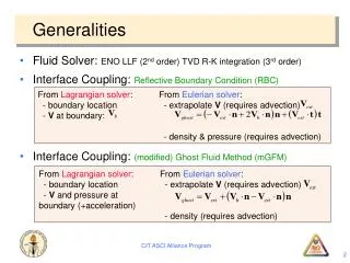
Semiconductors : generalities Energyloss by a chargedparticle : Bethe-Bloch Standard : Energyloss : electrons – holes pairs created (NOT electrons – ions…) If Field (evennatural) electrons migration Electrical pulse Information Too simple !
Semiconductors : generalities One MIP in Silicon at 300°K Energyloss :dE / dx ≈ 388 Ev/µm Ionisation Energy : 3.62 eV e – holes pairs created : 107/µm For 300 µm : 3.2 10 4pairs created Free charge carriers in the same volume : ≈ 4.5 10 9 Signal islost ! Solution : Depletion of the detector - Doping - Blocking contacts Depletion: removing the maximum possible thermally excitable electrons
Semiconductors : generalities : the Fano factor Number of e – h pairs is a statisticalprocess : Number of e-h pairs : N = E loss / Eionization If excitations are independants , theyobey to a Poisson statistic with a standard deviation variance : Fano factor : variance / mean of the process (shouldbe 1 for a perfect Poisson distribution) Fano factor related to energyresolution : A Fano factor < 1 meansthat the energyresolutionwouldbebetterthan Theoreticallyexpected…
Semiconductors : generalities : p and n types dopants : Boron, Arsenic, Phosphorous, Gallium
Semiconductors : generalities : p and n types Typically : doping level for a Silicon Detector : 10 12atoms / cm 3 Doping us usuallydone by ion implantation.
Semiconductors : generalities : junction detectors A p-n junction is formed when a single crystal of semiconductor is doped with acceptors on one side and donors on the other
Semiconductors : generalities : reverse biasingscheme The p – n zones willbeused for contact and to block (Blocking Contacts) the undesired noise
Semiconductors : generalities : building DC CouplingSilicon detector
Semiconductors : generalities : building AC CouplingSilicon detector
Semiconductors : generalities : building AC coupled Si detectors create 2 electrical circuits : - Read-out circuit to the amplifier (AC current) - Biasing circuit (DC current)
Semiconductors : generalities : building AC CouplingSilicon detector : bias voltage system
Semiconductors : Si detectors designs Most commonlyscheme AC + poly S-biasresistor
Semiconductors : Si detectors designs CMS design ATLAS design
Semiconductors : Radiation Damage Two types of radiation damage : Bulk (Crystal) damagedue to Non Ionizing Energy Loss (NIEL) - displacement damage, built up of crystal defects – Change of effective doping concentration (higher depletion voltage, under- depletion)Increase of leakage current (increase of noise, thermal runaway)Increase of charge carrier trapping (loss of charge) Surface damagedue to Ionizing Energy Loss (IEL) - accumulation of positive in the oxide (SiO2) and the Si/SiO2 interface –affects: interstrip capacitance (noise factor), breakdown behavior, … Impact on detector performance (depending on detector type and geometry and readout electronics!)Signal/noise ratio is the quantity to watch Sensors can fail from radiation damage !
Semiconductors : Effect of radiations Loss of collected charges (new 300 µm Silicon ≈ 24 000 e- for 1 MIP) Trapping is characterized by an effective trapping time eff for electrons and holes: where
Semiconductors : Effect of radiations Increase of Leakagecurrent
Semiconductors : Effect of radiations Change in depletion voltage and type inversion Innermost layers shouldstillworkafter before inversion p+ n+ n+ p+ after inversion
Semiconductors : 2-dimensional detectors Double SidedSilicon Detectors (DSSD) Not much in use…
Semiconductors : 2-dimensional detectors Stereo Modules
Semiconductors : Pixels Detectors Pixel sizes : ATLAS : 50 µm x 400 µm CMS : 100 µm x 150 µm ALICE : 50 µm x 425 µm
Semiconductors : Pixels Detectors CONNECTION BY BUMP BONDING
Semiconductors : Pixels Detectors Pitch : 50 µm (wirebondingtypically 200µm)
Semiconductors : Siliconhistory CDF NA 11 DELPHI CMS ≈ 215 m2 ATLAS ≈ 61 m2 LHCb ≈ 12.5 m2 CDF ≈ 3.5 m2 ALICE ≈ 1.5 m2
Semiconductors : Challenges and Evolutions Main Challenge : The LHC at High Luminosity (2024 ?) More tracks : Occupancyincreases - Lessresolution More Flux : Radiation (bulk) damage
Semiconductors : Challenges and Evolutions Reduce the Occupancy: Increase the granularity Mini-stripssensors (reducelenghtfrom 10 cm to 5 cm) - Increases the number of channels - Increases the cost - Increases the power to bedissipated Reduce the matérial: Thin Si sensors - Reduce the Charges Collected Reduce the number of layers - Reduce the overallTrackerefficiency 300 µm 150 µm
Semiconductors : Challenges and Evolutions Change the material: OxygenatedSilicon HE detectrors : FZ (Float Zone) Crystal - High resistivity > 3-4 kΩcm - O2 contens < 50 10 16 New Materials : DOFZ : O2 doped FZ Silicon (Oxydation of wafer at high temperature) MCZ (MagneticCzochralki) - Lessresistivity ≈ 1.5 kΩcm - O2 contens > 5 10 17 EPITAXIAL growth : ChemicalVaporDeposition on CZ substrate EPIlayer CZsubstrate Oxygen concentration in DOFZ Oxygen concentration in Epitaxial
Semiconductors : Challenges and Evolutions 24 GeV/c protonirradiation • Standard FZ silicon • type inversion at ~ 21013 p/cm2 • strong Neff increase at high fluence • Oxygenated FZ (DOFZ) • type inversion at ~ 21013 p/cm2 • reduced Neff increase at high fluence • CZ siliconand MCZ silicon • no type inversion in the overall fluence range (verified by TCT measurements) (verified for CZ silicon by TCT measurements, preliminary result for MCZ silicon) donor generation overcompensates acceptor generation in high fluence range • Common to all materials (after hadron irradiation): • reverse current increase • increase of trapping (electrons and holes) within ~ 20%
Semiconductors : Challenges and Evolutions MAPS (Monolithic Active Sensor) or CMOS (ComplementaryMetalOxideSemiconductor)
Semiconductors : Challenges and Evolutions 3D SiliconDetectors Manufacturing challenge Electrodes : dead zones Efficiency vs fluence
Semiconductors : Challenges and Evolutions DiamondisbetterthanSilicon Does not needany doping Better radiation hardness Better thermal conductivity Better speed Light insensitive Multi-metalization possible (test and physics) But : 3 times less signal for MIPs Difficult to manufacture Expensive Diamondis not understood (at the moment) Diamond detectors 2 forms : Polycristalline Wafer 6 inches Monocrystalline max : 4 x 4 mm 2
Semiconductors : Challenges and Evolutions Problem : Charge Collection Distance At LHC, need of 9000 – 1000 e- for an MIP : need a CCD ≥ 270 – 300 µm
Semiconductors : Challenges and Evolutions Stillplenty of questions about diamond: Somediamond are Schottky diodes (start to beconductive) ? On one side, diamondstarts to beconductive at + 100 V I(V) curve : leakagecurrent (2 faces) from - 500V to + 500V
Semiconductors : Challenges and Evolutions Stillplenty of questions about diamond: Influence of surface finishing Number of electronsmeasured on the samediamondwith 2 differentmetalization ? Metal( Au) by Evap : 14 000 e- Metal(Al) by Plasma : 16 000 e- Commercial : A 4-years program isunderway to prove the feasibility of diamond detectors for SLHC With LPSC –Grenoble and IPHC –Strasbourg (and other)