LINK EXISTING FACILITY
Status of the FAIR Synchrotrons Carsten Omet et al. (GSI Darmstadt, Planckstraße 1, D-64291 Darmstadt) . INTRODUCTION
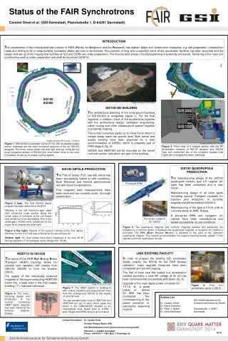

LINK EXISTING FACILITY
E N D
Presentation Transcript
Status of the FAIR SynchrotronsCarsten Omet et al. (GSI Darmstadt, Planckstraße 1, D-64291 Darmstadt) INTRODUCTION The construction of the modularized start version of FAIR (Facility for Antiproton and Ion Research) has started. Major civil construction measures, e.g. site preparation, construction roads and drilling of 60 m deep building foundation pillars are near to be finished. Procurement of long term production items of the accelerator facilities has been launched and the design and set-up of the magnet test facilities at GSI and CERN are under preparation. The final iteration phase of building planning is presently processed. Tendering of the main civil construction work is under preparation and shall be launched Q4/2014. Laser Cooling Acceleration Acceleration Bunch compression SIS100 SIS300 Image courtesy of FAIR GmbH Transfer SIS100 SIS300 SIS100/300 BUILDING The architectural planning of the underground building of SIS100/300 is completed (figure 1). For the final approval, a collision check of the accelerators together with the architectural design, ventilation engineering, cable routing and other infrastructure system together is presently ongoing. The tunnel comprises partly up to three floors which in certain areas reach the ground level. Both tunnel and supply building have been prepared for a later accommodation of SIS300, which is presently part of FAIR stage 6 (fig. 2). SIS300 and HEBT300 will be mounted on the tunnel roof with anchor rails which are part of the building. Extraction → to Experiments → Injection from SIS18 Images courtesy of M. Konradt / J. Falenski Figure 1: SIS100/300 accelerator tunnel (T110) with its parallel supply tunnel. Indicated are the main functional sections of the six SIS100 straights. The three niches (down left and right and up) comprise the local cryogenics system of SIS100/300. One further niche in the north is foreseen for set-up of a laser cooling system. Images courtesy of M. Konradt Figure 2: Front view of a straight section with the RF acceleration systems of SIS100 (bottom) and SIS300 (top) and connection box of the cryogenic bypass lines (right) which bridges the warm insertions. SIS100 QUADRUPOLE PRODUCTION The manufacturing design of the SIS100 quadrupole module type 2.5 (regular arc type) has been completed and is now frozen. Manufacturing design of all other types (including special Y-shaped cryostats for injection and extraction) is currently ongoing and will be finished Q3/2014. Manufacturing of the type 2.5 FoS units is currently starts at JINR, Russia. A pre-series BPM and cryogenic ion catcher have been manufactured and tested successfully at cold conditions. SIS100 DIPOLE PRODUCTION The First of Series (FoS, see left) article has been successfully tested at cold conditions. Both Electrical and thermal performances are well beyond expectations. First magnetic field measurements have been done and are currently under thorough examination. Pre-series BPM Image courtesy of Babckock Noell Figure 3 (top): The FoS SIS100 dipole magnet has been delivered in 06/2013. Winding of the stiff Nuclotron-type cable with enhanced cross section along the small radius of curvature at the coil heads has turned out to be demanding. Due to the small gap (143x68 mm²), tolerances for the super-ferric magnet are quite tight. Pre-seriescryogenic ion catcher Figure 5: Two quadrupole magnets and corrector magnets (steerer and sextupole) are installed on a common girder. In between the quadrupole magnets, a cryogenic ion catcher is mounted. The BPM (Beam Position Monitor) is attached to the yoke of the upstream quadrupole magnet. The module accommodates the superconducting busbar system of the dipoles and three quadrupole circuits. Figure 4 (top right): Results of the quench training of the FoS dipole. Nominal current (13,1 kA) was achieved at the second quench. Bottom right: AC heat losses have been measured to be only 45 W during operation (1 Hz triangular cycle; design limit: 55 W). LINK EXISTING FACILITY In order to prepare the existing GSI accelerator facility (mainly the SIS18) for the FAIR booster operation, major upgrade measures have been completed and are still ongoing. The first of three new MA loaded h=2 acceleration cavities providing a total RF voltage of 50 kV has been commissioned successfully with beam (fig. 8). Upgrade of the main dipole power converter for 10 T/s at a pulsepower of almost50 MW has beencontracted. Thecommissioning of the power converter isplanned for beginningof 2016. HEBT13/18/100/300 The layout of the FAIR High Energy Beam Transport (HEBT) topology allows for parallel user operation with beams from SIS100, SIS300 or from the booster SIS18. For supply of the individually powered magnets of the superconducting HEBT300 beam line, a large area in the main supply building 17.1 has been allocated. ← to S-FRS / pbar / APPA ← to CBM/HADES from SIS100/300 ← Image courtesy of L. Heyl Figure 8:First h=2 acceleration cavity in SIS18. Figure 7: The HEBT system in building 4 with vertical transfers and sloped beam lines from the underground SIS100 to the targets on ground level. The two parallel beam lines of HEBT100 and HEBT300 (on top of each other) guide the beam to the CBM/HADES situated on an intermediate level. Beam lines to S-FRS / pbar-Target and APPA rising to ground level. Figure 6: The manu-facturing design and Production of the normal conducting HEBT dipole magnets has been started at the Efremov Institute, Russia. Authors List Dr. Carsten Omet Dr. David Ondreka Dr. Peter J. Spiller Dr. Jens Stadlmann GSI HelmholtzzentrumfürSchwerionenforschung GmbH Planckstraße 1, 64291 Darmstadt Image courtesy of Efremov Contact Information: Dr. Carsten Omet Division Primary Beams (PB) GSI Helmholtzzentrum für Schwerionenforschung GmbH Planckstr. 1, D-64291 DarmstadtPhone: +49-6159-71-1385; Mail: C.Omet@gsi.de M-19