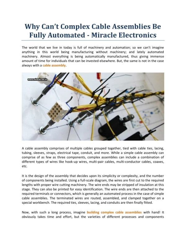
Automated Fixture Electronics
Automated Fixture Electronics Adding Fixture Electronic Boards into the board and board_xy By Thomas Garrison Background of Product High Volume (1M-2M a year) Next Generation product in panel of 24 Board level functional and ICT done at the same time

Automated Fixture Electronics
E N D
Presentation Transcript
Automated Fixture Electronics Adding Fixture Electronic Boards into the board and board_xy By Thomas Garrison
Background of Product • High Volume (1M-2M a year) Next Generation product in panel of 24 • Board level functional and ICT done at the same time • Reduce time at product level functional test
What needed to be done • Switch in 3 resistors for each board position • not enough GP relays to do this with • Each board to have one power supply muxed in • Also to have a series resistor • Keep test time, complexity, and maintenance low • Replacement easy and fast and done by anyone
Design Steps • Decided to use analog switches as control element • Smaller footprint than relays, shorting blocks • Might be able to use a small kit • Number of devices needed reduced • 18 Quad Switches vs 36 Dual relays • Decided to use analog switches and design board using ExpressPCB (http://www.expresspcb.com/) • Boards can be built be our internal house
What has to be part of the design • 18 Quad analog switches (max365) • 9 per module • 96 Resistors • 48 49 resistors • 24 10k resistors • 24 120 resistors for power supplies • ~152 wires had to be connected
Internal vs. External • External • Have to protect the circuitry • Probe points automatically generated for easier wiring • Good contact has to be maintained for each actuation • Internal • Everything away from prying eyes • Wiring more difficult with a ribbon cable • Have to remove interface plate to change or maintain
Design with ExpressPCB • 35 mil square test pads on bottom of the board • spaced at least 100 mil apart • .125 diameter tooling holes • SOIC16 chips for the switches • 1812 and 0603 chip resistors • Power supply resistors ½ watt through hole • Added extra breakaways for custom PCB for the 24 load resistors for the power supplies (boards placed internally) • Recorded X,Y locations of tooling locations and test pads in Excel file
Final Layout of PCB Board • Final Size 3x4 • 2 boards -- $102 • Components -- $80 • Layout 2-3 Hours
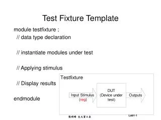
Adding to the Agilent Software • Started with Excel worksheet with netname, x, and y data for each point • Exported as a comma separated file (csv) • Wrote an awk script to convert csv to psuedo board and board_xy • Added Fixed node options to board file • Added outline to the board_xy
Editing the Board File • Take existing information and enclose it with Board <name> and end board • Connections, devices, and component information • Move existing fixed node information into this new board block • Leave rest outside of board block • header information, global options, pin maps • Add the new board(s) to the panel • Add the psuedo board file created before after end board and before end
Editing the board_xy • Enclose node, other,board tooling, and board outline in a board/end board block • Leave panel outline, panel tooling, board location and header information out • Add the new board location to the panel • Add psuedo board_xy after end board and before end • Edit the panel outline to include the fixture electronic boards
Automated wiring • The probe xy information for the fixture electronic boards is contained in the fixture • does not allow shorts between boards to exist • I file with nodes that needed to be connected • Ex. 25:RC_IN1 1:/N$1497 • Then I wrote an awk script to go through the fixture files to get a xy and brc locations for each the p-pins associated with those nodes • Generate psuedo wires file for the fixture vendor to use with their semi-automated wire wrap machine
The Fixture • Electronics board actuated once • Vacuum is persistent • Everything needed to actuate vacuum again is inside fixture • Need a tester power supply connected through a relay • To release vacuum remove the restraining bars • To add vacuum again • place fixture on the testhead • turn vacuum on • turn on the power supply and close relay • after board actuated add restraining bars