Refinery Structure- Evolution
Refinery Structure- Evolution. Mainly fractionation by distillation For production of industrial fuels. Topping Refinery. Hydro treating units added for fuels quality improvement . Hydroskimming Refinery. Addition of several conversion processes to improve: fuels recovery efficiency,

Refinery Structure- Evolution
E N D
Presentation Transcript
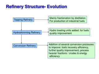
Refinery Structure- Evolution Mainly fractionation by distillation For production of industrial fuels Topping Refinery Hydro treating units added for fuels quality improvement Hydroskimming Refinery Addition of several conversion processes to improve: fuels recovery efficiency, further quality improvement, process heavier fractions / crudes & energy efficiency Conversion Refinery
Processing of light crude Processing of light crude, even in a complex/modern refinery with FCC, hydrocracking etc. does not yield a satisfactory product distribution. The amounts of fuel oil are too high.
Processing of heavy oil • For heavy oil the situation is even worse with ~ 50% fuel oil being produced even in a complex /modern refinery. • Fuel oil is worth < original crude. The value of the products decreases in the order: gasoline> kerosene/gas oil > crude oil > fuel oil. Bottom of the barrel treatment is vital Challenge – Meeting Strict Quality standards & Increasing Demand
Petroleum Refining- Types of Operations Fractionation (distillation)- • Separation of crude oil in atmospheric and vacuum distillation towers into groups of hydrocarbon compounds of differing boiling-point ranges called "fractions" or "cuts." Conversion Processes • Changing the size and/or structure of hydrocarbon molecules via different processes: • Decomposition (dividing) by thermal and catalytic cracking; • Unification (combining) through alkylation and polymerization; and • Alteration (rearranging) with isomerization and catalytic reforming. Treatment Processes • For additional processing and to prepare finished products. • Removal or separation of aromatics / naphthenes/ impurities / undesirable contaminants. • Chemical or physical separation e.g. dissolving, absorption, or precipitation • Desalting, drying, hydro de-sulfurization, sweetening, solvent refining, solvent extraction, and solvent de-waxing.
Petroleum - Properties Density Specific gravity - Ratio of mass of specific volume to mass of the same volume of water, both at the same temperature API Gravity Degrees API = (141.5/Specific gravity at 60/60 °F) – 131.5 Viscosity- cP- Flow characteristics Kinematic viscosity/fluidity = Viscosity/ Specific gravity Carbon residue (wt%) • Carbonaceous residue left out after destructive distillation- non-volatile part of petroleum/petroleum products • Ramsbottom method- ASTM D 189 IP3 • Conradson method - ASTM D 189 IP4 • Viscosity and Asphaltenes, Nitrogen & Sulfur contents increase with increasing carbon residue • Indicates the potential for coke formation Signify Light/Heavy character of Crude oil
Petroleum - Properties Aniline point • Temperature at which exactly equal parts of two components are • Miscible- Aniline & Any petroleum fraction/oil • Increases slightly with molecular weight • Increases rapidly with paraffinic character/ • Higher the aniline point- lower is the aromatics content in the fraction • Reid vapor pressure (RVP) • A measure of the volatility of gasoline. It is defined as the absolute • vapor pressure exerted by a liquid at 100 °F (37.8 °C) as determined • by the test method ASTM-D-323. • RVP differs slightly from the True Vapor pressure (TVP) of a liquid • due to some small sample vaporization and the presence of water • vapor and air in the confined space of the test equipment, i.e. the RVP • is the absolute vapor pressure and the TVP is the partial vapor pressure
Petroleum - Properties Cloud point • The temperature of the test specimen at which wax crystals have formed sufficiently to be observed as a cloud from a petroleum fraction • Applicable for petroleum products and biodiesel fuels • An index of the lowest temperature of their utility for certain applications. • Petroleum blending operations require a precise measurement of the cloud point. Smoke point • Provides an indication of the relative smoke producing properties of kerosines and aviation turbine fuels in a diffusion flame. • Related to the hydrocarbon type composition of such fuels, esp. aromatics • More aromatic the fuel the smokier the flame. • A high smoke point indicates a fuel of low smoke producing tendency. • The smoke point is quantitatively related to the potential radiant heat transfer from the combustion products of the fuel.
Petroleum- Properties Pour point • The lowest temperature at which it will pour or flow under prescribed conditions. It is a rough indication of the lowest temperature at which oil is readily pumpable. • Can be defined as the minimum temperature of a liquid, particularly a lubricant, after which, on decreasing the temperature, the liquid ceases to flow. UOP K factor ( Watson Characterization factor) K = 3√ TB/ S TB- Average molal BP in Deg.Rankine ; S- Sp.gravity at 60°F
Crude Assay- Properties that determine the processibility, product pattern & hence the cost of the crude
These fractions need go through regular refining processes to yield fuels of acceptable grade
Thermal Processes: Cracking & Coking
Desalting Objectives Removal of water, inorganic salts, water soluble metals & suspended solids from crude oil –Prevention of corrosion, fouling & plugging of equipments Process Two stage desalting is carried out, with removal of most of the water at first stage, followed by addition of dilution water in the second stage to extract soluble salts & metals. Process conditions are 90-150°C and 50-250 psi. Surfactants are added to demulsify & achieve proper separation and remove water by settling. Application of electrostatic coalescing is also adopted • Effective desalting • 1 kg salt/1000 bbl • Chlorides 10-30 ppm
Thermal cracking Dubbs process- Universal Oil Products (UOP) • Thermal cracking of reduced crude at 455-540°C & 100 -1000 psi • Major products- Gasoline & middle distillates • Soaking of light & heavier fractions & further cracking • Thermal cracking of Reduced crude oil • Feedstock; API gravity 25 °C ; IBP- 227°C • Cracking parameters- 500 °C ; Soaker pressure; 225 psi • Product yields (Vol%) With recycle of H. Oil W/o recycle of Heating oil Gas - 1.0 Naphtha 57.5 42.0 Heating oil 0.0 23.0 Residuum 37.5 34.0
Visbreaking • Process • Viscosity-breaking- Cracking to reduce the viscosity • A mild form of thermal cracking of the residue (10% conversion), at 50-300 psig • pressure at 455-520°C to reduce viscosity/ pour point. • Liquid phase cracking. Process optimized to minimize coke formation • Water injected with the feed to provide turbulance & control temperature • Residue from Atmos. / Vac. distillation units can be used • Coil/Furnace type- high temp. & short residence time • Soaker type- Lower temp. & longer residence time • Benefits • 5-10% conversion leads to 5 fold decrease in viscosity • Reduction in pour point • Less coke formation vis-a vis other processes • Blending of LHO to FO minimized • Product stability is the issue- Olefinics
Visbreaking- Process variations Hydrovisbreaking Treatment with hydrogen at mild conditions 3 reactors: 1. Visbreaking- Mild cracking with H2 2. Demetallation 3. Hydrocracking Reactors 2 & 3 use Co-Mo-Alumina catalyst for removal of metals and cracking of heavier molecules. Less Coke formation Better quality product- demetallized Aquaconversion Catalytic process in slurry mode Oil soluble catalyst and water Alkali metal catalysts activate the transfer of hydrogen from water as H+ Coke formation is reduced
Delayed coking • The feed is subjected to thermal cracking, in a coke drum, under high pressure & temperature-15-90 psig & 415-450 °C • Held (delayed) ~24 hours for the process to get completed • Two coke drums used, one for processing and the other for coke removal & cleaning • Virtually eliminates residue fraction-forms solid carbon/fuel • Highly aromatic coke, retains S,N & metals • Naphtha, LGO & HGO – used for gasoline/diesel/FCCU after hydrotreating
Fluid Coking & Flexi Coking • Both FLUID COKING (1954) and FLEXICOKING (1976) use fluid bed technology • Thermally convert heavy oils such as vacuum residue, atmospheric residue, • tar sands bitumen, heavy crudes, deasphalter bottoms & other heaviers • Heat for the process is supplied by partial combustion of coke. Remaining coke is • withdrawn as product • Feed is injected into a fluidised bed with hot coke particles. Steam is injected at the • bottom for fluidization • New coke formed is deposited as a thin layer on the surface of circulating coke • particles; Coking vessel temp-480-565°C;residence time 15-30 sec. • FLEXICOKING goes one step beyond FLUID COKING: in addition to • generating clean liquids, FLEXICOKING also produces a low-BTU (90 BTU/Cu.ft • or 800 Kcal/m3) gas in one integrated processing step that can virtually eliminate • petroleum coke production. ~ 95 % coke conversion is achieved
Fluid coking- Flexibility Feed Quality- Conradson carbon- 15.5; Gravity I°API- 6.4, LV below 1000°F-8.0%; S- 2.6 %; N- 1.0 %; Ni- 283 ppm; V-126 ppm Low ReactorTemp High ReactorTemp Yields Hydrogen sulfide 0.5 0.7 H2 0.1 0.2 C1-C3 8.0 9.0 C4 1.6 2.0 C5-215°F 4.2 5.1 215-400°F 8.6 10.4 400°F to End point 58.4 51.8 Gross coke 18.5 20.2 Net coke 10.0 10.6 Coke Sulfur % 3.4 3.4 Ni ppm 1520 1400 V ppm 680 620
Liquid products from thermal processing require further treatments for use as fuels MS Rana et.al. Fuel,86,1216,2007
Propane deasphalting • Generic name- Solvent Deasphalting (SDA) to yield DeAsphalted Oil (DAO)-Feeds- Vac residue/bitumen • Coke-forming tendencies of heavier distillation products are reduced by removal of asphaltenic materials by solvent extraction. • Liquidpropane is a good solvent. Butane, pentane, Heptane or mixture of solvents are also commonly used. • Vacuum residue is fed to a counter current deasphalting tower. • Deasphalting is based on solubility of hydrocarbons in propane, i.e. the type of molecule; Alkanes dissolve in propane whereas asphaltenic materials (aromatic compounds), ‘coke-precursors’ do not. • Asphalt is sent for thermal processing. • Deasphalted oil can be used as Lube oil base feedstock (LBFS) or as feed to FCCU
Propane deasphalting • DAO from propane de-asphalting has the highest quality but lowest yield, possibly due to low critical temp.97°C & Max extraction temp-82 °C • Mixtures of propane & n-butane more suitable for better extraction. • Using pentane may double or triple the yield from a heavy feed, but at the expense of contamination by metals and carbon residues that shorten the life of downstream cracking catalysts due to their increased solubility. • Choice of solvent & extraction conditions are critical
Propane deasphalting Propane/Oil ratio- 6:1 to 10:1 by vol.
Deasphalting process - Data SUS-Sabolt Universal Seconds –ASTM D 2161-Related to kinematic viscosity