Grade Sensor Placement
Grade Sensor Placement. Asphalt Paving Grade Sensor Placement. Grade Sensor Placement. Where should a Grade Sensor be placed on the screed? Topcon Grade Sensors: Sonic Tracker Contacting Sensor Smoothtrac SAS Laser Receiver mmGPS Receiver


Grade Sensor Placement
E N D
Presentation Transcript
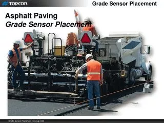
Grade Sensor Placement Asphalt Paving Grade Sensor Placement
Grade Sensor Placement • Where should a Grade Sensor be placed on the screed? • Topcon Grade Sensors: • Sonic Tracker • Contacting Sensor • Smoothtrac SAS • Laser Receiver • mmGPS Receiver • Fore and Aft Placement in reference to the tow arm • Front, middle, or rear? • End gate or Tow arm?
Grade Sensor Placement • Where should a Grade Sensor be placed on the screed? • Rear of screed is desired grade position, relative to the grade reference • The grade sensor needs to measure and control the screed position • Grade control is adjusted by the cylinder at the front of the screed tow arm • The grade sensor needs to measure the changes that have been made Grade Adjustment Desired Grade Curb – Grade Reference
Grade Sensor Placement • Where should a Grade Sensor be placed on the screed? • The tow cylinder moves immediately as grade adjustments are made • The screed will change grade as the screed moves forward Grade Adjustment Desired Grade Curb – Grade Reference
Grade Sensor Placement • Where should a Grade Sensor be placed on the screed? • The tow cylinder moves immediately as grade adjustments are made • The screed will change grade as the screed moves forward Grade Adjustment Desired Grade Curb – Grade Reference
Grade Sensor Placement • Where should a Grade Sensor be placed on the screed? • The grade sensor needs to measure and control the screed position • The grade sensor needs to measure the changes that have been made ? Grade Adjustment Desired Grade Curb – Grade Reference
Grade Sensor Placement • Grade Sensor placed at the back of the screed • The grade sensor needs to measure and control the screed position Grade Adjustment Desired Grade Curb – Grade Reference
Grade Sensor Placement • Grade sensor positioned at the back of the screed • No feedback indicating the tow point position has changed • Tracker continues to apply grade corrections Grade Adjustment Desired Grade ? Curb – Grade Reference
Grade Sensor Placement • Grade sensor at the back of screed • Will produce long waves • A grade sensor can not be placed at the back of the screed X Curb – Grade Reference
Grade Sensor Placement • Grade Sensor placed at the tow cylinder • The grade sensor needs to have position feedback from the cylinder it is controlling • The grade sensor can keep the tow point exactly at the desired grade Grade Adjustment Curb – Grade Reference
Grade Sensor Placement • Grade Sensor placed at the tow cylinder • Changes in the forces acting on the screed still exist! • Manually adjusting the thickness adjustment screws changes screed height • Grade sensor continues to control tow cylinder keeping it on desired path • The grade sensor does not see changes in screed position Increase in material height Pivot point Screed rises Curb – Grade Reference
Grade Sensor Placement • Grade sensor at tow cylinder • No correction for changes in screed height • A grade sensor can not be placed at the tow cylinder X Curb – Grade Reference
Grade Sensor Placement • Where should a Grade Sensor be placed on the screed? • The grade sensor needs to measure and control the screed position • The grade sensor needs to measure the changes that have been made Grade Adjustment Screed position Curb – Grade Reference
Grade Sensor Placement • Rule of Thumb = Middle 1/3 of the tow arm • Sensor has feedback of screed height • Sensor has feedback of grade control changes 1/3 1/3
Grade Sensor Placement • Sensor placement affects screed reaction • Grade sensor maintains distance to the grade reference • Sensor position becomes control pivot point = effective tow arm length 9’ effective tow arm length 3’ Grade Reference d
Grade Sensor Placement • Grade sensor at rear 1/3 of screed - Step disturbance change in grade • Sensor sees step disturbance, unit of 1 • Sensor drives the tow cylinder until the sensor raises 1 unit • Tow cylinder raises 3 units = large change in screed angle of attack effective tow arm length 3’ d
Grade Sensor Placement • Step disturbance change in grade – Sensor raises unit of 1 • With increased angle of attack, screed begins to raise • Grade Sensor lowers cylinder to maintain desired distance from reference • After 1 tow arm length (3’), screed has risen 63% of the grade change One tow arm length d
Grade Sensor Placement • Step disturbance change in grade – Sensor raises unit of 1 • Grade Sensor continues to lower cylinder as the screed rises to maintain desired distance from reference • After 2 tow arm lengths (6’), screed has risen 87% of the grade change One tow arm length One tow arm length d
Grade Sensor Placement • Step disturbance change in grade – Sensor raises unit of 1 • Grade Sensor continues to lower cylinder as the screed rises to maintain desired distance from reference • After 3 tow arm lengths, screed has risen 95% of the grade change 9’ d
Grade Sensor Placement • Sensor placed farther back – Screed is more reactive • Screed quickly and accurately follows grade reference • Jobs with quick changes in grade; city streets, parking lots, etc. 9’ effective tow arm length 3’
Grade Sensor Placement • Grade sensor forward, 2/3 of screed - Step disturbance change in grade • Sensor sees step disturbance, unit of 1 • Sensor drives the tow cylinder until the sensor raises 1 unit • Tow cylinder raises 1.5 units = small change in screed angle of attack effective tow arm length 6’ d
Grade Sensor Placement • Grade sensor forward, 2/3 of screed - Step disturbance change in grade • After 3 tow arm lengths, screed has risen 95% of the grade change 18’ 6’ 6’ 6’
Grade Sensor Placement • Sensor placed farther forward – Screed is less reactive • Screed is slower to respond to grade deviations • Jobs where smoothness is primary concern • Good job practice regarding Principles of Paving is more critical 9’ effective tow arm length 6’
Grade Sensor Placement • What is the best place to mount a grade sensor – Tow arm or end gate? • Two primary factors; • Stability of sensor • Grade reference location
Grade Sensor Placement • Tow arm or end gate? • In theory, the tow arm and the screed extensions are one rigid unit • As tow arm raises and lowers, extensions and end gate move together tow arm tow arm tow arm end gate end gate end gate
Grade Sensor Placement • Flex between tow arm and end gate can occur • Wear in crank and adjustment bushings • As screed extension is extended out, physical structure is not as strong tow arm tow arm tow arm end gate
Tow Arm or End Gate? • Two primary factors • Stability of sensor – Tow arm is always best choice • Grade reference location – When the grade reference changes position relative to the paver, such as curbs with lane changes, the end gate is a more practical solution
mmGPS or Laser Sensor Mounting • Tow arm is always best choice • Laser receiver or mmGPS – Grade reference location is not a problem • Stability of the sensor is primary concern
Grade Sensor Placement Asphalt Paving Grade Sensor Placement