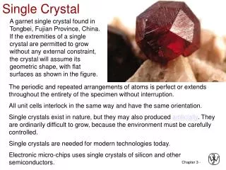
Single Crystal Slip
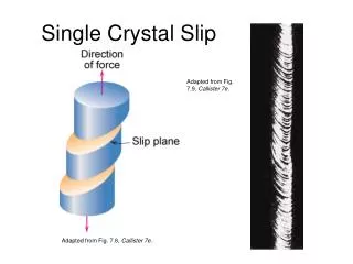
Single Crystal Slip. Adapted from Fig. 7.9, Callister 7e. Adapted from Fig. 7.8, Callister 7e. Calculation of Theoretical Shear Stress for a Perfect Lattice. G. Dieter, Mechanical Metallurgy, 3rd Edition , McGraw-Hill , 1986. Dislocation Concept.

Single Crystal Slip
E N D
Presentation Transcript
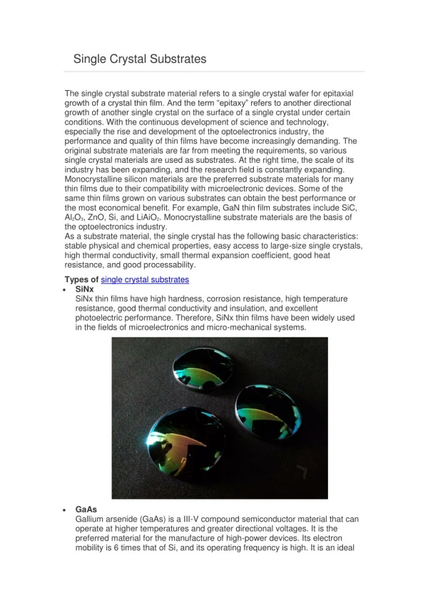
Single Crystal Slip Adapted from Fig. 7.9, Callister 7e. Adapted from Fig. 7.8, Callister 7e.
Calculation of Theoretical Shear Stress for a Perfect Lattice G. Dieter, Mechanical Metallurgy, 3rd Edition, McGraw-Hill, 1986.
Dislocation Concept • Concept of dislocation was first introduced to explain the discrepancy between observed and theoretical shear strengths • For the dislocation concept to be valid: • The motion of a dislocation through a lattice must require less stress than the theoretical shear stress • The movement of dislocations must produce steps or slip bands at free surfaces
Cottrell Energy Argument • Plastic deformation is transition from unslipped to slipped state • The process is opposed by an energy barrier • To minimize energy the slipped material will grow by advance of an interfacial region (dislocation) • To minimize energy of transition – interface thickness, w, small • Distance w is width of dislocation • Smaller w – lower interfacial energy • Larger w – lower elastic energy of the crystal – atomic spacing in the slip direction is closer to atomic spacing • Equilibrium width is a balance of these two components G. Dieter, Mechanical Metallurgy, 3rd Edition, McGraw-Hill, 1986.
Peierls-Nabarro Force • Dislocation width determines the force required to move a dislocation through a crystal lattice • Peierls stress is the shear stress required to move a dislocation through a crystal lattice • Note: wide dislocations require lower stress to move • Makes sense: Wide – the highly distorted region at core is not localized on any particular atom • In ductile metals the dislocation width is on the order of 10 atomic spacings a is distance between slip planes b is the distance between atoms in the slip direction In ceramics with directional covalent bonds – high interfacial energy, dislocations are narrow – relatively immobile Combined with restrictions on slip systems imposed by electrostatic forces – low degree of plasticity
Dislocation Motion • Metals: Disl. motion easier. -non-directional bonding -close-packed directions for slip. + + + + + + + + + + + + + + + + + + + + + + + + electron cloud ion cores • Covalent Ceramics (Si, diamond): Motion hard. -directional (angular) bonding • Ionic Ceramics (NaCl): Motion hard. -need to avoid ++ and - - neighbors. - - - + + + + - - - - + + + - - - + + + +
Dislocation Motion Dislocations & plastic deformation • Cubic & hexagonal metals - plastic deformation by plastic shear or slip where one plane of atoms slides over adjacent plane by defect motion (dislocations). • If dislocations don't move, deformation doesn't occur! Adapted from Fig. 7.1, Callister 7e.
Dislocation Motion • Dislocation moves along slip plane in slip direction perpendicular to dislocation line • Slip direction same direction as Burgers vector Edge dislocation Adapted from Fig. 7.2, Callister 7e. Screw dislocation
Definition of a Slip System • Slip plane - plane allowing easiest slippage: • Minimize atomic distortion (energy) associated with dislocation motion • Wide interplanar spacings - highest planar atomic densities (Close Packed) • Slip direction- direction of movement • Highest linear atomic densities on slip plane
Independent Slip Systems • The number of independent slip systems is the total possible number of combinations of slip planes and directions Example: FCC • Slip occurs on {111} planes (close-packed) in <110> directions (close-packed) • 4 Unique {111} planes • On each plane 3 independent ‹110› • Total of 12 slip systems in FCC
Slip Systems • Some slip systems in BCC are only activated at high temperatures • BCC and FCC have many possible slip systems – ductile materials • HCP: Less possible slip systems – brittle material
Applied tensile Relation between Resolved shear s s tR stress: = F/A and tR stress: = F /A s s F tR slip plane normal, ns FS /AS = A l f F cos A / cos tR f nS F AS slip direction l A FS FS AS slip direction F slip direction tR Stress and Dislocation Motion • Crystals slip due to a resolved shear stress, tR. • Applied tension can produce such a stress.
Critical Resolved Shear Stress typically 10-4GPa to 10-2 GPa s s s tR s = 0 tR /2 = 0 tR = f l =90° l =90° =45° f =45° Schmid’s Law • Condition for dislocation motion: • Crystal orientation can make it easy or hard to move dislocation Schmid Factor maximum at = = 45º
Ex: Deformation of single crystal a) Will the single crystal yield? b) If not, what stress is needed? =60° So the applied stress of 6500 psi will not cause the crystal to yield. crss = 3000 psi =35° Adapted from Fig. 7.7, Callister 7e. = 6500 psi
So for deformation to occur the applied stress must be greater than or equal to the yield stress Ex: Deformation of single crystal What stress is necessary (i.e., what is the yield stress, sy)?