Download
1 / 1
10 likes | 174 Vues
Ultrafast X-ray Study of Swirling Hollow-Cone Sprays in the Near-Field. Advanced Photon Source, Argonne National Laboratory, US. Objectives. Ultrafast X-ray Phase-Enhanced Imaging. High Energy X-ray : 9.62keV.

E N D
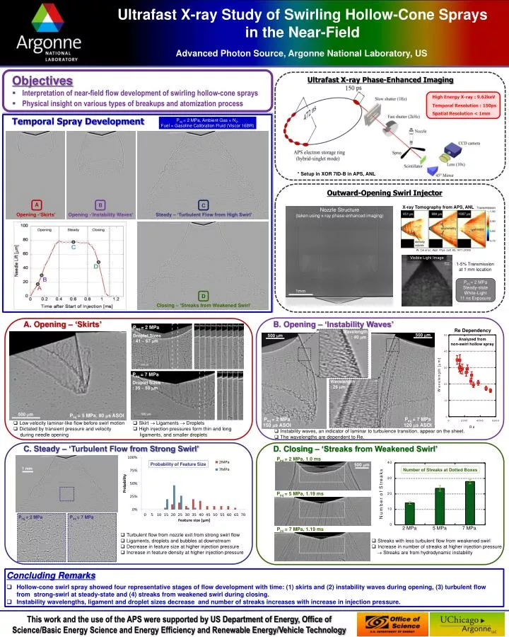
Ultrafast X-ray Study of Swirling Hollow-Cone Sprays in the Near-Field Advanced Photon Source, Argonne National Laboratory, US Objectives Ultrafast X-ray Phase-Enhanced Imaging High Energy X-ray : 9.62keV • Interpretation of near-field flow development of swirling hollow-cone sprays • Physical insight on various types of breakups and atomization process Temporal Resolution : 150ps Spatial Resolution < 1mm Temporal Spray Development Pinj= 2 MPa, Ambient Gas = N2, Fuel = Gasoline Calibration Fluid (Viscor 16BR) * Setup in XOR 7ID-B in APS, ANL Outward-Opening Swirl Injector A B C X-ray Tomography from APS, ANL Nozzle Structure (taken using x-ray phase-enhanced imaging) Opening -‘Skirts’ Opening -‘Instability Waves’ Steady – ‘Turbulent Flow from High Swirl’ D W. Caiet al., Appl. Phys. Lett. 83, 1671 (2003) Visible Light Image 1-5% Transmission at 1 mm location Pinj= 2 MPa Steady-state White-Light 11 ns Exposure 1mm Closing – ‘Streaks from Weakened Swirl’ A. Opening – ‘Skirts’ B. Opening – ‘Instability Waves’ Pinj= 2 MPa Droplet Sizes : 41 ~ 67 m Re Dependency Wavelength : 40 m 500 m 500 m Analyzed from non-swirl hollow spray Pinj= 7 MPa Droplet Sizes : 35 ~ 50 m Wavelength : 26 m 500 m Pinj= 5 MPa, 80 s ASOI Pinj= 7 MPa 120 s ASOI Pinj= 2 MPa 150 s ASOI • Low velocity laminar-like flow before swirl motion • Dictated by transient pressure and velocity • during needle opening • Skirt Ligaments Droplets • High injection pressures form thin and long • ligaments, and smaller droplets • Instability waves, an indicator of laminar to turbulence transition, appear on the sheet. • The wavelengths are dependent to Re. C. Steady – ‘Turbulent Flow from Strong Swirl’ D. Closing – ‘Streaks from Weakened Swirl’ Pinj= 2 MPa, 1.0 ms Probability of Feature Size 500 m 1 mm Number of Streaks at Dotted Boxes Pinj= 5 MPa, 1.19 ms 2 MPa 5 MPa 7 MPa Pinj= 2 MPa Pinj= 7 MPa Pinj= 7 MPa, 1.19 ms • Turbulent flow from nozzle exit from strong swirl flow • Ligaments, droplets and bubbles at downstream • Decrease in feature size at higher injection pressure • Increase in feature density at higher injection pressure • Streaks with less turbulent flow from weakened swirl • Increase in number of streaks at higher injection pressure • Streaks are from hydrodynamic instability • Concluding Remarks • Hollow-cone swirl spray showed four representative stages of flow development with time: (1) skirts and (2) instability waves during opening, (3) turbulent flow from strong-swirl at steady-state and (4) streaks from weakened swirl during closing. • Instability wavelengths, ligament and droplet sizes decrease and number of streaks increases with increase in injection pressure.