Download
1 / 26
260 likes | 421 Vues
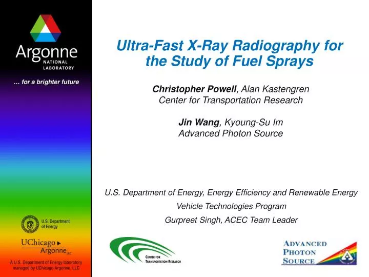
Ultra-Fast X-Ray Radiography for the Study of Fuel Sprays. Christopher Powell , Alan Kastengren Center for Transportation Research Jin Wang , Kyoung-Su Im Advanced Photon Source. U.S. Department of Energy, Energy Efficiency and Renewable Energy Vehicle Technologies Program

E N D
Ultra-Fast X-Ray Radiography for the Study of Fuel Sprays Christopher Powell, Alan Kastengren Center for Transportation Research Jin Wang, Kyoung-Su Im Advanced Photon Source U.S. Department of Energy, Energy Efficiency and Renewable Energy Vehicle Technologies Program Gurpreet Singh, ACEC Team Leader
Why Use X-Rays to Study Sprays? Visible Light Imaging Scattering is difficult to interpret X-Ray Radiography Number of x-rays absorbed indicates the quantity of fuel.
Schematic of X-Ray Setup I I0 I0 Incident x-ray intensity I Measured x-ray intensity mM Fuel absorption constant M Mass of fuel in x-ray beam Direct relation between x-ray intensity and fuel mass
X-Ray Detectors • Cornell Pixel Array Detector • Fast (100 ns) 2D imaging • Marginal spatial resolution (150 mm) • Expensive prototype, limited access • Susceptible to radiation damage (lifetime about 5 days) • Avalanche Photodiode • Fast (1 ns), robust, inexpensive • Zero-D, must raster to form image. Tedious • Enables excellent spatial resolution (15 mm) • Continuous readout, captures complete time history
Time History of X-Ray Flux 0.2 mm from Nozzle Spray Enters Beam Spray Leaves Beam
Recent Accomplishments • Development of technique to measure fuel average speed • Previous measurements at leading and trailing edges • “Internal” fuel speed as a function of time • Single-shot measurements of spray • Previous measurements were all averaged • Measurements of Caterpillar HEUI injector • Production 6-hole nozzle • Measurements of biofuel sprays
Measurement of Fuel Velocity • Internal fuel velocity affects penetration, atomization, exchange of momentum with ambient gas • Accurate measurement crucial for numerical modeling • Exit velocity may be useful in validating models of flow inside the orifice • Need spray velocity for spray breakup models • Dynamic measurements of velocity would be particularly useful • How does spray velocity change as the needle opens/closes? • Existing techniques are limited: • Discharge coefficient, laser two-focus, laser flow tagging, LDV/PDPA • Ballistic imaging • All are limited near-nozzle or don’t provide transient measurement
Average Fuel Speed Found by Control Volume Analysis Control Volume • Fuel enters only from left side, doesn’t exit • We have time-dependent measurement of quantity of fuel (M1, M2,…) • Can determine mass flux M2 - M1 / t2 - t1 • We measure quantity of fuel in slice through spray, mass/thickness Injector Spray
Measurement of Fuel Speed Speed At Nozzle Exit • Speed of fuel emerging from nozzle increases over time as needle opens and pressure at orifice increases • Fuel speed is highest when it emerges from nozzle, slows as it moves downstream • Fuel speed crucial for spray modeling • Relates to exchange of momentum with ambient gas • Both KH and RT atomization models rely on this quantity 33 ms After SOI
Measurement of Instantaneous Fuel Speed • Two nozzles show similar speeds • Early in spray event, needle may not be fully open
Single-Shot Measurements - Repeatability of Start of Injection 2 mm from nozzle, 500 bar
Single-Shot Measurements - Repeatability of End of Injection 0.2 mm from nozzle, 500 bar
Measurements of Caterpillar Heavy-Duty HEUI Injector • Goal: Link spray measurements with engine performance • Measure sprays under “engine-like” conditions. Vary injection pressure, nozzle geometry. • Measure how changes in spray affect engine performance • 6-hole production nozzle • Utilizes Argonne’s strengths in engine measurement: performance, in-cylinder imaging, emissions. • Requires modeling to link spray measurements with engine data
Near Nozzle Spray Penetration Speed is Slow • Slower penetration speeds observed than with Bosch Common Rail systems • Further data analysis is ongoing • Engine will be running before the end of the year • Ambient density and fuel delivery will be matched between x-ray and engine measurements • Spray and Engine modeling work is beginning. 19
Ethanol • Low energy content • Lower viscosity, lubricity • Bio-Diesel • Fewer aromatics, more esters • Higher viscosity, lubricity • Vegetable Oils • Very high viscosity • Short shelf life, acid content • Hydrogen • Generation & storage • Consumer perception Alternative Choices for Transportation Fuel • Each fuel is expected to gain market share • Engine must adapt to optimize performance and meet emissions for a variety of fuels • What are the effects on sprays?
Experiment Parameter Matrices HydroGround Non-Ground 23
Experiment Conditions Simulate an Operating Engine • Measurements at ambient pressure of 30 bar are now routine • Gas density inside the spray chamber exceeds that of a light-duty diesel at TDC • Long-term tests of x-ray pressure windows shows they are capable of further pressure increase Light-Duty Heavy-Duty X-Ray Experiments
Future Plans • Measurements of Caterpillar injector have demonstrated feasibility of using production 6-hole injectors • Build adapter to mount 3- and 6-hole Bosch Injectors in Caterpillar chamber • Shield to isolate spray of interest • Update fuel system to accommodate Bosch Generation 2 and 3 injectors • Use hardware common to GM-Fiat 1.9 liter • Study conditions that match in-cylinder density, injection pressure • Engine is running at Argonne, other labs also have this engine • Will enable direct comparison between x-ray measurements and Argonne’s full suite of engine diagnostics: in-cylinder imaging, emissions, performance.
Presentations and Publications, FY2007 • “Measurement Of Diesel Spray Axial Velocity X-ray Radiography”, Alan Kastengren, Advanced Engine Combustion MOU Meeting, February 2007, SNL. • “Fuel Spray Characterization Using Ultra-Fast X-Ray Radiography”, Christopher Powell, UIC Mechanical Engineering Graduate Council, March 2007, Chicago, IL. • “Determination of Diesel Spray Axial Velocity Using X-Ray Radiography”, Alan Kastengren, SAE Congress, April 2007, Detroit, MI. • “Improved Method to Determine Spray Axial Velocity Using X-Ray Radiography”, Alan Kastengren, ILASS, May 2007, Chicago, IL. • “Structure Of High-velocity Dense Sprays In The Near-Nozzle Region” F. X. Tanner, K. A. Feigl, S. A. Ciatti, C. F. Powell, S.-K. Cheong, J. Liu, J. Wang, Atomization and Sprays 16 579-597, 2006. • “Determination of Diesel Spray Axial Velocity Using X-Ray Radiography”, Alan Kastengren, SAE Congress, April 2007, Detroit, MI. • “Improved Method to Determine Spray Axial Velocity Using X-Ray Radiography”, Alan Kastengren, ILASS, May 2007, Chicago, IL. • “Spray Density Measurements Using X-Ray Radiography”, A. L. Kastengren and C. F. Powell, J. Auto. Eng. Special Edition. Accepted for publication. • “X-Ray Measurements of the Mass Distribution in the Dense Primary Break-Up Region of the Spray from a Standard Multi-Hole Common-Rail Diesel Injection System”, P. Leick, T. Riedel et al., ILASS-Europe, Sep 2007, Muğla, Turkey. • “Nozzle Geometry and Injection Duration Effects on Diesel Sprays Measured by X-Ray Radiography”, A.L. Kastengren et al., Submitted to J. Fluids Eng. • “Study Of Diesel Jet Variability Using Single-shot X-ray Radiography”, A. L. Kastengren, C. F. Powell, Y. Wang, J. Wang, Submitted to ASME.