Download
1 / 14
150 likes | 693 Vues
Chapter 5 Orthographic Views in Multiview Drawings. Learning Objectives: Create 2D orthographic views using AutoCAD. Using the CONSTRUCTION LINE command to draw. Using Running Object Snaps. Use AutoCAD’s AutoSnap and AutoTrack features. Create a Miter line to transfer dimensions.

E N D
Chapter 5 Orthographic Views in Multiview Drawings Learning Objectives: • Create 2D orthographic views using AutoCAD. • Using the CONSTRUCTION LINEcommand to draw. • Using Running Object Snaps. • Use AutoCAD’s AutoSnap and AutoTrack features. • Create a Miter line to transfer dimensions. • Using Projection lines between orthographic views. • Use the POLAR Tracking option.
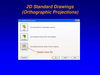
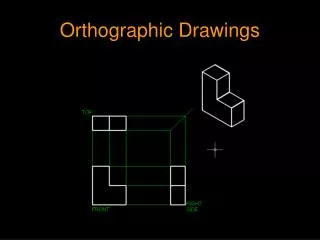
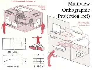
Introduction Most drawings produced and used in industry are multiview drawings. Multiview drawings are used to provide accurate three-dimensional object information on two-dimensional media, a means of communicating all of the information necessary to transform an idea or concept into reality. The standards and conventions of multiview drawings have been developed over many years, which equip us with a universally understood method of communication. The age of computers has greatly altered the design process, and several CAD methods are now available to help generate multiview drawings using CAD systems. Multiview drawings usually require several orthographic views to define the shape of a three-dimensional object. Each orthographic view is a two-dimensional drawing showing only two of the three dimensions of the three-dimensional object. Consequently, no individual view contains sufficient information to completely define the shape of the three-dimensional object. All orthographic views must be looked at together to comprehend the shape of the three-dimensional object. The arrangement and relationship between the views are therefore very important in multiview drawings. In this chapter, the common methods of creating two-dimensional orthographic views with AutoCAD are examined.
Drawing Construction Lines Construction lines are lines that extend to infinity. Construction lines are usually used as references for creating other objects. We will also place the construction lines on the Construction layer so that the layer can later be frozen or turned off.