Download
1 / 39
3.02k likes | 6.63k Vues
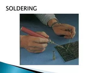
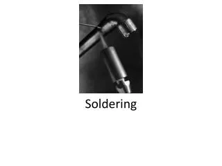
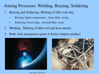
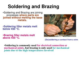
Soldering and Brazing. Soldering and Brazing are joining processes where parts are joined without melting the base metals. Soldering filler metals melt below 450 °C. Brazing filler metals melt above 450 °C. . (De)soldering a contact from a wire.

E N D
Soldering and Brazing Soldering and Brazing are joining processes where parts are joined without melting the base metals. Soldering filler metals melt below 450 °C. Brazing filler metals melt above 450 °C. (De)soldering a contact from a wire • Soldering is commonly used for electrical connection or mechanical joints, but brazing is only used for mechanical joints due to the high temperatures involved
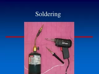
Soldering • A method of joining metal parts using an alloy of low melting point (solder) below 450 °C (800 °F). • Heat is applied to the metal parts, and the alloy metal is pressed against the joint, melts, and is drawn into the joint by capillary action and around the materials to be joined by 'wetting action'. • After the metal cools, the resulting joints are not as strong as the base metal, but have adequate strength, electrical conductivity, and water-tightness for many uses.
Soldering and Brazing Benefits • Economical for complex assemblies • Joints require little or no finishing • Excellent for joining dissimilar metals • Little distortion, low residual stresses • Metallurgical bond is formed • Sound electrical component connections
Soldering can be done in a number of ways Including passing parts over a bulk container of melted solder, using an infrared lamp, or by using a point source such as an electricsoldering iron, a brazing torch, or a hot-air soldering tool. A flux is usually used to assist in the joining process. Flux can be manufactured as part of the solder in single or multi-core solder, in which case it is contained inside a hollow tube or multiple tubes that are contained inside the strand of solder. Flux can also be applied separately from the solder, often in the form of a paste. In some fluxless soldering, a forming gas that is a reducing atmosphere rich in hydrogen can also serve much the same purpose as traditional flux, and provide the benefits of traditional flux in re-flow ovens through which electronic parts placed on a circuit card are transported for a carefully timed period of time.
One application of soldering is making connections between electronic parts and printed circuit boards. • Another is in plumbing. Joints in sheet-metal objects such as cans for food, roof flashing, and drain gutters were also traditionally soldered. • Jewelry and small mechanical parts are often assembled by soldering. • Soldering can also be used as a repair technique to patch a leak in a container or cooking vessel.
Soldering is distinct from welding in that the base materials to be joined are not melted, though the base metal is dissolved somewhat into the liquid solder much as a sugar cube into coffee - this dissolution process results in the soldered joint's mechanical and electrical strengths. • A "cold solder joint" with poor properties will result if the base metal is not warm enough to melt the solder and cause this dissolution process to occur.
Due to the dissolution of the base metals into the solder, solder should never be reused • Once the solder's capacity to dissolve base metal has been achieved, the solder will not properly bond with the base metal and a cold solder joint with a hard and brittle crystalline appearance will usually be the result. • It is good practice to remove solder from a joint prior to resoldering - desoldering wicks or vacuum desoldering equipment can be used. • Desoldering wicks contain plenty of flux that will lift the contamination from the copper trace and any device leads that are present. This will leave a bright, shiny, clean junction to be resoldered.
The lower melting point of solder means it can be melted away from the base metal, leaving it mostly intact through the outer layer. • It will be "tinned" with solder. • Flux will remain which can easily be removed by abrasive or chemical processes. • This tinned layer will allow solder to flow into a new joint, resulting in a new joint, as well as making the new solder flow very quickly and easily.
Common joining problems and discontinuities: • No wetting • Excessive wetting • Flux entrapment • Lack of fill (voids, porosity) • Unsatisfactory surface appearance • Base metal erosion
Basic electronic soldering techniques All solder pads and device terminals must be clean for good wetting and heat transfer. The soldering iron or gun must be clean, otherwise components may heat up excessively due to poor heat transfer. The devices must then be mounted on the circuit board properly. One technique is to elevate the components from the board surface (a few millimeters) to prevent heating of the circuit board during circuit operation. After device insertion, the excess leads can be cut leaving only a length equal to the radius of the pad. Plastic mounting clips or holders are used for large devices to reduce mounting stresses.
Heat sink the leads of sensitive devices to prevent heat damage. • Apply soldering iron or gun to both terminal lead and copper pad to equally heat both. • Apply solder to both lead and pad but never directly to the tip of soldering iron or gun. • Direct contact will cause the molten solder to flow over the gun and not over the joint. • The moment the solder melts and begins to flow, remove the solder supply immediately. • Do not remove the iron yet. The remaining solder will then flow over the junction of the lead and pad, assuming both are free of dirt. • Let the iron heat the junction until the solder flows and then remove the iron tip. This will ensure a good solid junction. • Remove the iron from the junction and let the junction cool. Solder flux will remain and should be removed.
Be sure not to move the joint while it is cooling. Doing so will result in a fractured joint. • Do not blow air onto the joint while it is cooling; Instead, let it cool naturally, which will occur fairly rapidly. • A good solder joint is smooth and shiny. The lead outline should be clearly visible. Clean the soldering iron tip before you begin on a new joint. It is absolutely important that the iron tip be free of residual flux. • Excess solder should be removed from the tip. This solder on the tip is known as keeping the tip tinned. It aids in heat transfer to the joint. • After finishing all of the joints, remove excess flux residue from the board using alcohol, acetone, or other organic solvents. • Individual joints can be cleaned mechanically. • The flux film fractures easily with a small pick and can be blown away with canned air. • In solder formulations with water-soluble fluxes, sometimes pressurized carbon dioxide or distilled water are used to remove flux.
Traditional solder for electronic joints is a 60/40 Tin/Lead mixture with a rosin based flux that requires solvents to clean the boards of flux. • Environmental legislation in many countries, and the whole of the European Community area, have led to a change in formulation. • Water soluble non-rosin based fluxes have been increasingly used since the 1980's so that soldered boards can be cleaned with water or water based cleaners. This eliminates hazardous solvents from the production environment, and effluent.
Lead-free electronic soldering • More recently environmental legislation has specifically targeted the wide use of lead in the electronics industry. The directives in Europe require many new electronic circuit boards to be lead free by 1st July 2006, mostly in the consumer goods industry, but in some others as well. • Many new technical challenges have arisen, with this endeavour.
For instance, traditional lead free solders have a significantly higher melting point than lead based solders, which renders them unsuitable for use with heat sensitive electronic components and their plastic packaging. To overcome this problem solder alloys with a high silver content and no lead have been developed with a melting point slightly lower than traditional solders. • Not using lead is also extended to components pins and connectors. Most of those pins were using copper frames, and either lead, tin, gold or other finishes. Tin-finishes is the most popular of lead-free finishes. However, this poses nevertheless the question of tin-whiskers. Somehow, the current movement brings the electronic industry backs to the problems solved 40 years ago by adding lead. • A new classification to help lead-free electronic manufacturers decide what kind of provisions they want to take against whiskers, depending upon their application criticity.
Stained glass soldering • Historically soldering tips were copper, placed in braziers. One tip was used; when the heat had transferred from the tip to the solder (and depleted the heat reserve) it was placed back in the brazier of charcoal and the next tip was used. • Currently, electric soldering irons are used; they consist of coil or ceramic heating elements, which retain heat differently, and warm up the mass differently, internal or external rheostats, and different power ratings - which change how long a bead can be run. • Common solders for stained glass are mixtures of tin and lead, respectively: • 60/40: melts between 361°-376°F • 50/50: melts between 368°-421°F • 63/37: melts between 355°-365°F • lead-free solder (useful in jewelry, eating containers, and other environmental uses): melts around 490°F
Pipe/Mechanical soldering • Sometimes it is necessary to use solders of different melting points in complex jobs, to avoid melting an existing joint while a new joint is made. • Copper pipes used for drinking water should be soldered with a lead-free solder, which often contains silver. Leaded solder is not allowed for most new construction, though it is easier to create a solid joint with that type of solder. The immediate risks of leaded solder are minimal, since minerals in municipal or well water supplies almost immediately coat the inside of the pipe, but lead will eventually find its way into the environment. • Tools required for pipe soldering include a blowtorch (typically propane), wire brushes, a suitable solder alloy and an acid paste flux, typically based on zinc chloride. Such fluxes should never be used on electronics or with electronics tools, since they will cause corrosion of the delicate electronic part.
Soldering defects • Soldering defects are solder joints that are not soldered correctly. • These defects may arise when solder temperature is too low. • When the base metals are too cold, the solder will not flow and will "ball up", without creating the metallurgial bond. • An incorrect solder type (for example, electronics solder for mechanical joints or vice versa) will lead to a weak joint. • An incorrect or missing flux can corrode the metals in the joint. Without flux the joint may not be clean. • A dirty or contaminated joint leads to a weak bond. A lack of solder on a joint will make the joint fail. • An excess of solder can create a "solder bridge" which is a short circuit. Movement of metals being soldered before the solder has cooled will make the solder appear grainy and may cause a weakened joint. • Soldering defects in electronics can lead to short circuits, high resistance in the joint, intermittent connections, components overheating, and damaged circuit boards. Flux left around integrated circuits' leads will lead to inter-lead leakage. • It is a big issue on surface mount components and causes improper device operation as moisture absorption rises. In mechanical joints defects lead to joint failure and corrosion
Soldering processes • Wave soldering • Reflow soldering • Infrared soldering • Induction soldering • Ultrasonic soldering • Dip soldering • Furnace soldering • Iron soldering • Resistance soldering • Torch soldering • Silver soldering/Brazing
Brazing • Is similar to soldering but uses higher melting temperature alloys, based on copper, as the filler metal. • "Hard soldering", or "silver soldering" (performed with high-temperature solder containing up to 40% silver) is also a form of brazing, and involves solders with melting points above 450 C. Even though the term "silver soldering" is more often used than silver brazing, it is technically incorrect. • Since lead used in traditional solder alloys is toxic, much effort in industry has been directed to adapting soldering techniques to use lead-free alloys for assembly of electronic devices and for potable water supply piping.
Brazing • Brazing is a joining process whereby a non-ferrous filler metal and an alloy are heated to melting temperature (above 450°C;) and distributed between two or more close-fitting parts by capillary action. • At its liquid temperature, the molten filler metal interacts with a thin layer of the base metal, cooling to form an exceptionally strong, sealed joint due to grain structure interaction. T • he brazed joint becomes a sandwich of different layers, each metallurgically linked to each other. • Common brazements are about 1/3 as strong as the materials they join, because the metals partially dissolve each other at the interface, and usually the grain structure and joint alloy is uncontrolled. • To create high-strength brazes, sometimes a brazement can be annealed, or cooled at a controlled rate, so that the joint's grain structure and alloying is controlled.
In Braze Welding or Fillet Brazing, a bead of filler material reinforces the joint. A braze-welded tee joint is shown here. • In another common specific similar usage, brazing is the use of a bronze or brass filler rod coated with flux, together with an oxyacetylene torch, to join pieces of steel. The American Welding Society prefers to use the term Braze Welding for this process, as capillary attraction is not involved, unlike the prior silver brazing example. • Braze welding takes place at the melting temperature of the filler (e.g., 870 °C to 980 °C for bronze alloys) which is often considerably lower than the melting point of the base material (e.g., 1600 °C for mild steel).
A variety of alloys of metals, including silver, tin, zinc, copper and others are used as filler for brazing processes. • There are specific brazing alloys and fluxes recommended, depending on which metals are to be joined. Metals such as aluminum can be brazed though aluminum requires more skill and special fluxes. It conducts heat much better than steel and is more prone to oxidation. • Some metals, such as titanium cannot be brazed because they are insoluble with other metals, or have an oxide layer that forms too quickly at intersoluble temperatures.
Although there is a popular belief that brazing is an inferior substitute for welding, this is false. • For example, brazing brass has a strength and hardness near that of mild steel, and is much more corrosion-resistant. • In some applications, brazing is indisputably superior. For example, silver brazing is the customary method of joining high-reliability, controlled-strength corrosion-resistant piping such as a nuclear submarine's seawater coolant pipes. • Silver brazed parts can also be precisely machined after joining, to hide the presence of the joint to all but the most discerning observers, whereas it is nearly impossible to machine welds having any residual slag present and still hide joints.
In order to work properly, parts must be closely fitted and the base metals must be exceptionally clean and free of oxides for achieving the highest strengths for brazed joints. • For capillary action to be effective, joint clearances of 0.002 to 0.006 inch (50 to 150 µm) are recommended. In braze-welding, where a thick bead is deposited, tolerances may be relaxed to 0.5 mm. • Cleaning of surfaces can be done in several ways. Whichever way is selected, it is vitally important to remove all grease, oils, and paint. For custom jobs and part work, this can often be done with fine sand paper or steel wool. • In pure brazing (not braze welding), it is vitally important to use sufficiently fine abrasive. Coarse abrasive can lead to deep scoring that interferes with capillary action and final bond strength. Residual particulates from sanding should be thoroughly cleaned from pieces. • In assembly line work, a "pickling bath" is often used to dissolve oxides chemically. Dilute sulfuric acid is often used. Pickling is also often employed on metals like aluminum that are particularly prone to oxidation.
In most cases, flux is required to prevent oxides from forming while the metal is heated. The most common fluxes for bronze brazing are borax-based. T • he flux can be applied in a number of ways. It can be applied as a paste with a brush directly to the parts to be brazed. Commercial pastes can be purchased or made up from powder combined with water (or in some cases, alcohol). Alternatively, brazing rods can be heated and then dipped into dry flux powder to coat them in flux. • Brazing rods can also be purchased with a coating of flux. In either case, the flux flows into the joint when the rod is applied to the heated joint. Using a special torch head, special flux powders can be blown onto the workpiece using the torch flame itself. • Excess flux should be removed when the joint is completed. Flux left in the joint can lead to corrosion. • During the brazing process, flux may char and adhere to the work piece. Often this is removed by quenching the still-hot workpiece in water (to loosen the flux scale), followed by wire brushing the remainder.
Brazing is different from welding,where even higher temperatures are used, the base material melts and the filler material (if used at all) has the same composition as the base material. • Given two joints with the same geometry, brazed joints are generally not as strong as welded joints. Careful matching of joint geometry to the forces acting on the joint, however, can often lead to very strong brazed joints. • The butt joint is the weakest geometry for tensile forces. The lap joint is much stronger, as it resists through shearing action rather than tensile pull and its surface area is much larger. To get joints roughly equivalent to a weld, a general rule of thumb is to make the overlap equal to 3 times the thickness of the pieces of metal being joined. • The "welding" of cast iron is usually a brazing operation, with a filler rod made chiefly of nickel being used although true welding with cast iron rods is also available.
Vacuum brazing is another materials joining technique, one that offers extremely clean, superior, flux free braze joints while providing high integrity and strength. • The process can be expensive because it is performed inside a vacuum chamber vessel however, the advantages are significant. For example, furnace operating temperatures, when using specialized vacuum vessels, can reach temperatures of 2400 °C. Other high temperature vacuum furnaces are available ranging from 1500 °C and up at a much lesser cost. • Temperature uniformity is maintained on the work piece when heating in a vacuum, greatly reducing residual stresses because of slow heating and cooling cycles. • This, in turn, can have a significant impact on the thermal and mechanical properties of the material, thus providing unique heat treatment capabilities. • One such capability is heat treating or age hardening the work piece while performing a metal-joining process, all in a single furnace thermal cycle. Reference: M.J.Fletcher, “Vacuum Brazing”. Mills and Boon Limited: London, 1971.
Advantages over welding • The lower temperature of brazing and brass-welding is less likely to distort the work piece or induce thermal stresses. For example, when large iron castings crack, it is almost always impractical to repair them with welding. In order to weld cast-iron without recracking it from thermal stress, the work piece must be hot-soaked to 1600 °F. When a large (more than fifty kilograms (100 lb)) casting cracks in an industrial setting, heat-soaking it for welding is almost always impractical. Often the casting only needs to be watertight, or take mild mechanical stress. Brazing is the premium, preferred repair method in these cases. • The lower temperature associated with brazing vs. welding can increase joining speed and reduce fuel gas consumption. • Brazing can be easier for beginners to learn than welding. • For thin workpieces (e.g., sheet metal or thin-walled pipe) brazing is less likely to result in burn-through.
Brazing can also be a cheap and effective technique for mass production. Components can be assembled with preformed plugs of filler material positioned at joints and then heated in a furnace or passed through heating stations on an assembly line. The heated filler then flows into the joints by capillary action. • Braze-welded joints generally have smooth attractive beads that do not require additional grinding or finishing. • The most common filler materials are gold in colour, but fillers that more closely match the color of the base materials can be used if appearance is important.
Possible problems • A brazing operation may cause defects in the base metal, especially if it is in stress. This can be due either to the material not being properly annealed before brazing, or to thermal expansion stress during heating. • An example of this is the silver brazing of copper-nickel alloys, where even moderate stress in the base material causes intergranular penetration by molten filler material during brazing, resulting in cracking at the joint. • Any flux residues left after brazing must be thoroughly removed; otherwise, severe corrosion may eventually occur.
Brazing processes • Block Brazing • Diffusion Brazing • Dip Brazing • Exothermic Brazing • Flow Brazing • Furnace Brazing • Induction Brazing • Infrared Brazing • Resistance Brazing • Torch Brazing • Twin Carbon Arc Brazing • Vacuum Brazing
A rivet is a permanent mechanical fastener. Before being installed a rivet consists of a smooth cylindrical shaft with a head on one end. The end opposite the head is called the buck-tail. On installation the rivet is placed in a punched or pre-drilled hole, and the tail is upset, or bucked (i.e. deformed), so that it expands to about 1.5 times the original shaft diameter, holding the rivet in place. To distinguish between the two ends of the rivet, the original head is called the factory head and the deformed end is called the shop head or buck-tail. Because there is effectively a head on each end of an installed rivet, it can support tension loads (loads parallel to the axis of the shaft); however, it is much more capable of supporting shear loads (loads perpendicular to the axis of the shaft). Bolts and screws are better suited for tension applications. Fastenings used in traditional wooden boat building, like copper nails and clinch bolts, work on the same principle as the rivet but were in use long before the term rivet came about and, where they are remembered, are usually classified among the nails and bolts respectively.
This bridge is one of the finest cantilever bridges in the world - a gift to India from the Purulian engineers. Howrah bridge, links the city of Howrah to its twin city, Kolkata (Calcutta). On 14 June 1965 it was renamed Rabindra Setu, after Rabindranath Tagore the first Indian Nobel laureate. However it is still popularly known as the Howrah Bridge.
The bridge is 705 metres long and 30 metres wide. More than 26,500 MT of high-tensile steel went into this unique bridge supported by two piers, each nearly 90 meters above the road. An engineering marvel, it expands as much as a metre during a summer day. This is constructed entirely by riveting, without nuts or bolts
Riveted Truss over Orange River. This river is the longest river in South Africa. It rises in the Drakensberg mountains in Lesotho, flowing westwards through South Africa to the Atlantic Ocean. The river forms part of the international borders between South Africa and Namibia and between South Africa and Lesotho, as well as several provincial borders within South Africa.