Download
1 / 54
610 likes | 835 Vues
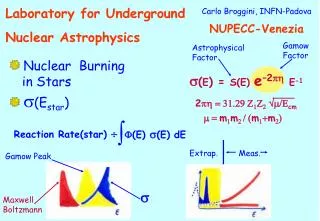
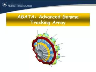
Advance Gamma Tracking Array AGATA Dino Bazzacco INFN Padova. Part 1: Review of AGATA Part 2: Data Processing. EGAN school 2011, December 5 - 9, 2011, Liverpool. Shape coexistence. Transfermium nuclei. 100 Sn. 48 Ni. 132+x Sn. 78 Ni. Challenges in Nuclear Structure.

E N D
Advance Gamma Tracking Array AGATA Dino BazzaccoINFN Padova Part 1: Review of AGATA Part 2: Data Processing EGAN school 2011, December 5 - 9, 2011, Liverpool
Shape coexistence Transfermium nuclei 100Sn 48Ni 132+xSn 78Ni Challenges in Nuclear Structure • Shell structure in nuclei • Structure of doubly magic nuclei • Changes in the (effective) interactions • Proton drip line and N=Z nuclei • Spectroscopy beyond the drip line • Proton-neutron pairing • Isospin symmetry • Nuclear shapes • Exotic shapes and isomers • Coexistence and transitions • Neutron-rich heavy nuclei (N/Z → 2) • Large neutron skins (rn-rp→ 1fm) • New coherent excitation modes • Shell quenching • Nuclei at the neutron drip line (Z→25) • Very large proton-neutron asymmetries • Resonant excitation modes • Neutron Decay
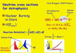
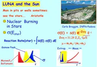
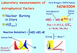
Requirements for the gamma detectors • Best possible energy resolution in the range 10 keV – 10 MeV to disentangle complex spectra • Germanium detectors are the obvious choice • Good response function to maximize the number of good events • Large-volume Germanium detectors have at most 20% • Compton background suppression via BGO shields • Best possible effective energy resolution • Most experiments detect gammas emitted by nuclei moving at high speed (b ~5÷10% 50%) • Energy resolution dominated by Doppler broadening if the velocity vector and the emission angle of the g-ray are not well known • Good high solid angle coverage to maximize efficiency, ideally 4p • Good granularity to reduce multiple hits on the detectors in case of high g-ray multiplicity events • The individual crystals should be as big as possible to avoid dead materials that could absorb radiation • High counting rate capability
2. Response functionEscape-Suppressed Ge-detectors For large-volume Ge crystals the Anticompton shield (AC) improves the Peak_to_Totalratio (P/T) from ~20% to ~60% BGO counts In a g-g measurement, the fraction of useful peak-peak coincidence events grows from 4 % to 36% For high fold (F) coincidences the fraction of useful coincidences is P/T F 60Co keV
3. Effective Energy Resolution Doppler Broadening Eg 1 MeV DElab √(1.2+0.003*Elab) b(%) 5±0.01 20±0.005 DQ(deg) 8 2 DEg/Eg(%) Opening Recoil Intrinsic
How to improve our g-detection systems Idea of g-ray tracking Compton Shielded Ge large opening angle means poor energy resolution at high recoil velocity eph ~ 10% Ndet ~ 100 q~ 8º ~40% Ge Sphere too many detectors are needed to avoid summing effects eph ~ 50% Ndet ~ 1000 q~ 3º Ge Tracking Array • Combination of: • segmented detectors • digital electronics • pulse processing • tracking the g-rays eph ~ 50% Ndet ~ 100 q~ 1º ~80%
Gamma-Ray Tracking Paradigm A3 A4 A5 B3 B4 B5 Identification of hits inside the crystal C3 C4 C5 (x,y,z,E,t)i · measuredcalculated · · CORE · · · · · g Large Volume Segmented Germanium Detectors Reconstruction of individual gammas from the hits Decomposition of signal shapes Digital electronics Energy and direction of the gamma rays Thorsten Kröll
Aim of gamma-ray tracking • From the deposited energies and the positions of all the interactions points of an event in the detector, reconstruct individual photon trajectories and write out photon energies, incident and scattering directions • Discard events corresponding to incomplete energy release Doppler correction Linear Polarization e1, x1, y1,z1 e2, x2, y2,z2 ………………….. en, xn, yn,zn E1, (q,f)inc,1,(q,f)sc,1. … E2, (q,f)inc,2,(q,f)sc,2. … ……………………………… Ei, (q,f)inc,i,(q,f)sc,i
Interaction of photons in germanium Mean free path determines size of detectors: l( 10 keV) ~ 55 mm l(100 keV) ~ 0.3 cm l(200 keV) ~ 1.1 cm l(500 keV) ~ 2.3 cm l( 1 MeV) ~ 3.3 cm l( 2 MeV) ~ 4.5 cm l( 5 MeV) ~ 5.9 cm l(10 MeV) ~ 5.9 cm
Tracking of Compton Scattered Events Source position is known • Questions : • Is the event complete • What is the right sequence
Two 5-point events c2 Permutation number Tracking of Compton Scattering Events Find c2 for the N! permutations of the interaction points Fit parameter is the permutation number Accept the best permutation if its c2 is below a predefined value
Reconstruction of Pair-Production Eventsbased on recognition of first hit GEANT Spectrum Standard Shell Eg = 4 MeV Mg = 1 105 transitions spp/ stot = 25 % eph = 49 % P/T = 62 % Eg - m0c2 e = 1.5 % Spectrum of packed points eph = 6.4 % P/T = 99 % Pair Production Reconstructed Reconstruction Efficiency 74 % Eg-2m0c2 e = 8.7 % m0c2 e = 3.5 % 0.6 % 0.8
Reconstruction of single interaction events • There is not much we can do • Acceptance criterion is probabilistic: depth < k·l(e1)
Reconstruction of multi-gamma events • Analysis of all partitions of measured hits is not feasible:Huge computational problem(~1023 partitions for 30 points) Figure of merit is ambiguous the total figure of merit of the “true” partition not necessarily the minimum • Forward peaking of Compton scattering cross-section implies that the hits of one gamma tend to be localized along the emission direction • The most used algorithm (G.Schmid et al. NIMA 430 1999, GRETA) starts by identifying clusters of points which are then analyzed as individual candidates gammas, accepted as said before
Forward Tracking implemented in AGATA • Create cluster pool => for each cluster, Eg0 = cluster depositions • Test the 3 mechanisms • do the interaction points satisfythe Compton scattering rules ? • does the interaction satisfyphotoelectric conditions (e1,depth,distance to other points) ? • do the interaction points correspondto a pair productionevent ?E1st= Eg– 2 mec2 and the other points can be grouped in two subsets with energy ~ 511 keV ? • Select clusters based on c2
A high multiplicity event Eg = 1.33 MeV Mg = 30 27 gammas detected -- 23 in photopeak16 reconstructed -- 14 in photopeak Performance of the Germanium Shell Idealized configuration to determinemaximum attainable performance. Reconstruction by Cluster-Tracking Packing Distance: 5 mm Position Resolution: 5 mm (at 100 keV)
Identification is not 100% surespectra will always contain background The acceptance value determines the quality (P/T ratio) of the spectrum Often we use the R = Efficiency•PT to qualify the reconstructed spectra
g g’ e- gbr Fundamental effects limiting the performance • Interaction position position of energy deposition • Bremsstrahlung • Rayleigh scattering change incident direction (relevant at low energy & end of track) • Momentum profile of electron change scattering direction (relevant at low energy & end of track) Fortunately (?) these effects are masked by the poor position resolution of practical Ge detectors
x x x x x x x Practical Effects limiting the performance • uncertainty in position of interaction:(position & energy dependent) • position resolution • energy threshold • energy resolution • dead materials ...
Effect of energy-threshold on tracking efficiency Simulated spectrum x10 D E B C A Effect completely removed, if all hits in a crystal are assigned to the same gamma
Efficiency of Standard GeShellvs. Position Resolution and g Multiplicity The biggest losses are due to multiplicity (mixing of points) not to bad position resolution 5 mm is the standard “realistic” packing and smearing assumption Reminder: when quoting Position Resolution AGATA uses FWHM GRETA uses s If positions inside segments are not known, performance is “only” a factor 2 worse Standard shell; Eg = 1.33 MeV; Packing=Smearing; Energy independent smearing
Implementations of the concept • Specs • Configurations of 4p Arrays • Monte Carlo • The detectors • Status
Requirements for a Gamma Tracking Array efficiency, energy resolution, dynamic range, angular resolution, timing, counting rate, modularity, angular coverage, inner space
Building a Geodesic Ball (1) Start with a platonic solid e.g. the icosahedron On its faces, draw a regular pattern of triangles grouped as hexagons and pentagons. E.g. with 110 hexagons and (always) 12 pentagons Project the faces on the enclosing sphere; flatten the hexagons.
Building a Geodesic Ball (2) Al capsules 0.4 mm spacing 0.8 mm thick Al canning 2.0 mm spacing 1.0 mm thick A radial projection of the spherical tiling generates the shapes of the detectors. Ball with 180 hexagons. Space for encapsulation and canning obtained cutting the crystals. In the example, 3 crystals form a triple cluster Add encapsulation and part of the cryostats for realistic MC simulations
Geodesic Tiling of Sphereusing 60–240 hexagons and 12 pentagons 60 80 120 110 150 200 240 180
AGATA Monte Carlo Simulations • Using the C++ package GEANT4, with extended geometry classes • Geometry defined by an external program • GEANT4 has good models of low energy interaction mechanisms of g rays • Simulations take into account dead materials and possible inner detectors • Provides input to g-ray tracking programs which performs further actions (packing and smearing) to make results as realistic as possible Package written by EnricoFarnea, INFN Padova
Performance of the 2 Configurations 120 crystals GRETA 120 crystals packed in 30 4-crystal modules AGATA 180 crystals packed in 60 3-crystal modules 180 crystals
AGATA Crystals 80 mm 90 mm Volume ~370 cc Weight ~2 kg (the 3 shapes are volume-equalized to 1%) 6x6 segmented cathode
Agata Triple Cluster Integration of 111 high resolution channels Cold FET technology for all signals A. Wiens et al. NIM A 618 (2010) 223–233 D. Lersch et al. NIM A 640(2011) 133-138 Courtesy P. Reiter
Energy resolution AGATA triple cluster ATC2
GRETINA Quadruple Cluster 4 crystals in one cryostat 36 fold segmented crystals 2 types of crystal shape Cold FET for cores, warm for segments 148 high resolution channels per cluster A-type B-type Courtesy I-Yang Lee
First implementations of theg-ray tracking array concept AGATA Demonstrator @ LNL GRETINA at LBNL 15 crystals in 5 TC Commissioned in 2009 (with 3 TC) Experiments since 2010 (mostly with 4 TC) Completed with the 5th TC, May 2011 32 crystals ordered, ~ 18 accepted 28 crystals (+2 spares) in 7 quads Engineering runs started April 2011 Now taking data at LBNL, coupled the BGS
The big challenge:operating the Ge detectorsin position sensitive mode
Pulse shapes in segmented detectors(very schematic) For a non-segmented “true” coax, the shape depends on initial radius If cathode is segmented, “net” and “transient” shapes depend on the angular position of the interaction point
Ge Energy NaI Energy Region of Interest 288 keV 288keV 374keV 374 keV 662keV <110> <010> T30 T60 T90 Characterization of Ge detectorsto validate calculated signals U. Liverpool 920 MBq 137Cs source 1 mm diameter collimator
Pulse Shape Analysis concept A3 A4 A5 Result of Grid SearchAlgorithm B3 B4 B5 (10,25,46) C3 C4 C5 y B4 C4 CORE measuredcalculated D4 x A4 F4 E4 791 keV deposited in segment B4 z = 46 mm
Complications for PSA • Theoretical • No good theory for mobility of holes must be determined experimentally • Mobility of charge carriers depends on orientation of collection path with respect to the crystal lattice shape of signals depends on orientation of collection path with respect to the crystal lattice • Detectors for a 4p array have an irregular geometry, which complicates calculation of pulse shape basis • Effective segments are defined by electric field and follow geometrical segmentation only roughly • Position resolution/sensitivity is not uniform throughout the crystal • Practical/Computational • A basis calculated on a 1 mm grid contains ~ 400000 points, each one composed by 37 signals each one with > 50 samples (for a 10 ns time step) • Direct comparison of the experimental event to such a basis takes too much time for real time operation at kHz rate • Events with more than one hit in a segment are common, often difficult to identify and difficult to analyze • Low energy releases can easily end-up far away from their actual position
Position sensitivity • Position sensitivity is the minimum distance at which difference in pulse shapes become distinguishable over the noise. • It depends on the segmentation geometry, the segments size, the location within each segment and the direction. • An interaction at position iis distinguishable from one at j if the overall difference in signal shapes is greater than that caused by the random fluctuation (noise). • Noise level assumed to be 5 keV • c2 ~ 1 signals not distinguishable • c2 > 1 signals are distinguishable K.Vetter et al. NIMA 452(2000)223
Sensitivity inside crystals • Demonstration of sensitivity: the position sensitivity peaks at the effectivesegment borders. At the front, the deviation from the segmentation pattern is large. • Regions near the outer surface between segment borders have the poorest sensitivity total high dy dz dx low
Pulse Shape Analysis algorithms Singular Value Decomposition 8 Adaptive Grid Search Artificial Neural Networks Particle Swarm Optimization 6 Genetic algorithm now Position resolution (mm FWHM) Wavelet method 4 Least square methods Adaptive Grid Search(with final LS-fit refinements) 2 Full Grid Search 0 ms s hr Computation Time/event/detector
Adaptive Grid Search in action A B C D E F CC 1 2 3 4 5 6
Adaptive Grid Search in action A B C D E F CC Event with 3 net-charge segments (D1, D2, E3) 1 Initial residuals, after removing a hit at the center of the net charge segments 2 Largest net-charge segment passed to the search 3 Second net-charge segment searched after removing result of largest one 4 Smallest net-charge segment searched after removing result of the other two 5 Final residuals 6 Final Result
Performance of PSA • Depends on the signal decomposition algorithm but of equal or more importance are: • The quality of the signal basis • Physics of the detector • Impurity profile • Application of the detector response function to the calculated signals • The preparation of the data • Energy calibration • Cross-talk correction (applied to the signals or to the basis!) • Time aligment of traces • A well working decomposition has additional benefits, e.g. • Correction of energy losses due to neutron damage
Sum of segment Energies vs fold Energy [keV] Segment sum energies projected on fold 2folds : Core and Segment sumcentroidsvshitpattern …All possible 2fold combinations Crosstalkcorrection: Motivation • Crosstalk is present in any segmented detector • Creates strong energy shifts proportional to fold • Tracking needs segment energies !
Radiation damage from fast neutronsShape of the 1332 keV line 6 5 4 3 2 1 A B C D E F CC /150 White: April 2010 FWHM(core) ~ 2.3 keV FWHM(segments) ~2.0 keV Green: July 2010 FWHM(core) ~2.4 keV FWHM(segments) ~2.8 keV Damage after 3 high-rate experiments (3 weeks of beam at 30-80 kHz singles) Worsening seen in most of the detectors; more severe on the forward crystals; segments are the most affected, cores almost unchanged (as expected for n-type HPGe)
Crystal C002 corrected April 2010 July 2010 CCr=15mm SGr=15mm CCr=15mm SGr=15mm The 1332 keV peak as a function of crystall depth (z) for interactions at r = 15mm The charge loss due to neutron damage is proportional to the path length to the electrodes. The position is provided by the PSA, which is barely affected by the amplitude loss. Knowing the path, the charge trapping can be modeled and corrected away (Bart Bruyneel, IKP Köln)