Download
1 / 49
560 likes | 1.36k Vues
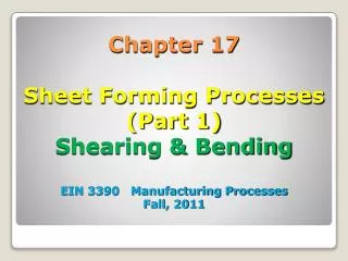
Chapter 17 Sheet Forming Processes (Part 1) Shearing & Bending EIN 3390 Manufacturing Processes Fall, 2011. Sheet metal processes involve plane stress loadings and lower forces than bulk forming Almost all sheet metal forming is considered to be secondary processing

E N D
Chapter 17Sheet Forming Processes(Part 1)Shearing & BendingEIN 3390 Manufacturing ProcessesFall, 2011
Sheet metal processes involve plane stress loadings and lower forces than bulk forming • Almost all sheet metal forming is considered to be secondary processing • The main categories of sheet metal forming are: • Shearing • Bending • Drawing 17.1 Introduction
Shearing- mechanical cutting of material without the formation of chips or the use of burning or melting • Both cutting blades are straight • Curved blades may be used to produce different shapes • Blanking • Piercing • Notching • Trimming 17.2 Shearing Operations
Fracture and tearing begin at the weakest point and proceed progressively or intermittently to the next-weakest location • Results in a rough and ragged edge • Punch and die must have proper alignment and clearance • Sheared edges can be produced that require no further finishing Shearing Operations
Shearing Operations Figure 17-1 Simple blanking with a punch and die.
Types of Shearing • Simple shearing- sheets of metal are sheared along a straight line • Slitting- lengthwise shearing process that is used to cut coils of sheet metal into several rolls of narrower width Figure 17-5 Method of smooth shearing a rod by putting it into compression during shearing. Figure 17-6 A 3-m (10ft) power shear for 6.5 mm (1/4-in.) steel. (Courtesy of Cincinnati Incorporated, Cincinnati, OH.)
Shearing Operations Figure 17-2 (Left) (Top) Conventionally sheared surface showing the distinct regions of deformation and fracture and (bottom) magnified view of the sheared edge. (Courtesy of Feintool Equipment Corp., Cincinnati, OH.)
Piercing and Blanking • Piercing and blanking are shearing operations where a part is removed from sheet material by forcing a shaped punch through the sheet and into a shaped die • Blanking- the piece being punched out becomes the workpiece • Piercing- the punchout is the scrap and the remaining strip is the workpiece Figure 17-8 (Above) (Left to Right) Piercing, lancing, and blanking precede the forming of the final ashtray. The small round holes assist positioning and alignment. Figure 17-7 Schematic showing the difference between piercing and blanking.
Fine Blanking - the piece being punched out becomes the workpiece and pressure pads are used to smooth edges in shearing Fine Blanking Operations Figure 17-3 (Top) Method of obtaining a smooth edge in shearing by using a shaped pressure plate to put the metal into localized compression and a punch and opposing punch descending in unison.
Shearing Operations Figure 17-4 Fineblanked surface of the same component as shown in Figure 17-2. (Courtesy of Feintool Equipment Corp., Cincinnati, OH.)
Lancing- piercing operation that forms either a line cut or hole • Perforating- piercing a large number of closely spaced holes • Notching- removes segments from along the edge of an existing product • Nibbling- a contour is progressively cut by producing a series of overlapping slits or notches Types of Piercing and Blanking
Types of Piercing and Blanking • Shaving- finishing operation in which a small amount of metal is sheared away from the edge of an already blanked part • Cutoff- a punch and a die are used to separate a stamping or other product from a strip of stock • Dinking- used to blank shapes from low-strength materials such as rubber, fiber, or cloth
Figure 17-10 The dinking process. Sheet-metal Shaving Operations Figure The shaving process.
Tools and Dies for Piercing and Blanking • Basic components of a piercing and blanking die set are: punch, die, and stripper plate • Punches and dies should be properly aligned so that a uniform clearance is maintained around the entire border • Punches are normally made from low-distortion or air-hardenable tool steel Figure 17-11 The basic components of piercing and blanking dies.
Figure 17-12 Blanking with a square-faced punch (left) and one containing angular shear (right). Note the difference in maximum force and contact stroke. The total work (the are under the curve) is the same for both processes. Blanking Operations
Figure 17-13 (Below) Typical die set having two alignment guideposts. (Courtesy of Danly IEM, Cleveland, OH.) Figure 17-14 (Above) A piercing and blanking setup using self-contained subpress tool units. (Courtesy of Strippit Division, Houdaille Industries, Inc., Akron, NY.) Blanking Operations
Progressive Die Sets • Progressive die sets- two or more sets of punches and dies mounted in tandem • Transfer dies move individual parts from operation to operation within a single press • Compound dies combine processes sequentially during a single stroke of the ram Figure 17-16 Progressive piercing and blanking die for making a square washer. Note that the punches are of different length.
Design rules • Diameters of pierced holes should not be less than the thickness of the metal with a minimum 0f 0.3 mm (0.025”) • Minimum distance between holes or the edge of the stock should be at least equal to the metal thickness • The width of any projection or slot should be at least 1 times the metal thickness and never less than 2.5 mm (3/32”) • Keep tolerances as large as possible • Arrange the pattern of parts on the strip to minimize scrap Design for Piercing and Blanking
The recommended clearance is: C = at Where c – clearance, in (mm); a – allowance; and t = stock thickness, in (mm). Allowance a is determined according to type of metal. From Mikell P. Groover “Fundamentals of Modern Manufacturing”. Clearance Calculation
For a round blank of diameter Db is determined as: Blank punch diameter = Db - 2c Blank die diameter = Db For a round hole (piercing) of diameter Dh is determined as: Hole punch diameter = Dh Hole die diameter = Db + 2c Design Die and Punch Sizes
Cutting forces are used to determine size of the press needed. F = StL Where S – shear strength of the sheet metal, lb/in2 (Mpa); t – sheet thickness in. (mm); and L – length of the cut edge, in. (mm). In blanking, punching, slotting, and similar operations, L is the perimeter length of blank or hole being cut. Note: the equation assumes that the entire cut along sheared edge length is made at the same time. In this case, the cutting force is a maximum. Cutting Forces
for slug or blank to drop through the die, the die opening must have an angular clearance of 0.25 to 1.50on each side. Angular Clearance
Round disk of 3.0” dia. is to be blanked from a half-hard cold-rolled sheet of 1/8” with shear strength = 45,000 lb/in2. Determine (a) punch and die diameters, and (b) blanking force. (a). From table , a = 0.075, so clearance c = 0.075(0.125) = 0.0094”. Die opening diameter = 3.0” Punch diameter = 3 – 2(0.0094) = 2.9812 in (b) Assume the entire perimeter of the part is blanked at one time. L = p Db = 3.14(3) = 9.426” F = 45,000(9.426)(0.125) = 53,021 lb Example for Calculating Clearance and Force
Design Example Figure 17-18 Method for making a simple washer in a compound piercing and blanking die. Part is blanked (a) and subsequently pierced (b) in the same stroke. The blanking punch contains the die for piercing.
17.3 Bending • Bending is the plastic deformation of metals about a linear axis with little or no change in the surface area • Forming- multiple bends are made with a single die • Drawing and stretching- axes of deformation are not linear or are not independent • Springback is the “unbending” that occurs after a metal has been deformed Figure 17-19 (Top) Nature of a bend in sheet metal showing tension on the outside and compression on the inside. (Bottom) The upper portion of the bend region, viewed from the side, shows how the center portion will thin more than the edges.
Angle Bending (Bar Folder and Press Brake) • Bar folders make angle bends up to 150 degrees in sheet metal • Press brakes make bends in heavier sheets or more complex bends in thin material Figure 17-22 Press brake dies can form a variety of angles and contours. (Courtesy of Cincinnati Incorporated, Cincinnati, OH.)
Bar Folder Figure 17-20 Phantom section of a bar folder, showing position and operation of internal components. (Courtesy of Niagara Machine and Tool Works, Buffalo, N.Y.)
Press Brake Figure 17-21 (Left) Press brake with CNC gauging system. (Courtesy of DiAcro Division, Acrotech Inc., Lake City, MN.) (Right) Close-up view of press brake dies forming corrugations. (Courtesy of Cincinnati Incorporated, Cincinnati, OH.)
Design for Bending • Several factors are important in specifying a bending operation • Determine the smallest bend radius that can be formed without cracking the metal • Metal ductility • Thickness of material Figure 17-24 Relationship between the minimum bend radius (relative to thickness) and the ductility of the metal being bent (as measured by the reduction in area in a uniaxial tensile test).
Considerationsfor Bending • If the punch radius is large and the bend angle is shallow, large amounts of springback are often encountered • The sharper the bend, the more likely the surfaces will be stressed beyond the yield point Figure 17-25 Bends should be made with the bend axis perpendicular to the rolling direction. When intersecting bends are made, both should be at an angle to the rolling direction, as shown.
Design Considerations • Determine the dimensions of a flat blank that will produce a bent part of the desired precision • Metal tends to thin when it is bent Figure 17-26 One method of determining the starting blank size (L) for several bending operations. Due to thinning, the product will lengthen during forming. l1, l2, and l3 are the desired product dimensions. See table to determine D based on size of radius R where t is the stock thickness.
Air-Bend, Bottoming, and Coining Dies • Bottoming dies contact and compress the full area within the tooling • Angle of the bend is set by the geometry of the tooling • Air bend dies produce the desired geometry by simple three-point bending • If bottoming dies go beyond the full-contact position, the operation is similar to coining Figure 17-27 Comparison of air-bend (left) and bottoming (right) press brake dies. With the air-bend die, the amount of bend is controlled by the bottoming position of the upper die.
Roll Bending • Roll bending is a continuous form of three-point bending • Plates, sheets, beams, pipes Figure 17-28 (Left) Schematic of the roll-bending process; (right) the roll bending of an I-beam section. Note how the material is continuously subjected to three-point bending. (Courtesy of Buffalo Forge Company, Buffalo, NY.)
Figure 17-29 (a) Draw bending, in which the form block rotates; (b) compression bending, in which a moving tool compresses the workpiece against a stationary form; (c) press bending, where the press ram moves the bending form. Draw Bending, Compression Bending, and Press Bending
Key parameters: outer diameter of the tube, wall thickness, and radius of the bend Figure 17-30 (a) Schematic representation of the cold roll-forming process being used to convert sheet or plate into tube. (b) Some typical shapes produced by roll forming. Tube Bending
Roll Forming • Roll forming is a process by which a metal strip is progressively bent as it passes through a series of forming rolls • Only bending takes place during this process, and all bends are parallel to one another • A wide variety of shapes can be produced, but changeover, setup, and adjustment may take several hours Figure 17-31 Eight-roll sequence for the roll forming of a box channel. (Courtesy of the Aluminum Association, Washington, DC.)
Seaming and Flanging • Seaming is a bending operation that can be used to join the ends of sheet metal in some form of mechanical interlock • Common products include cans, pails, drums, and containers • Flanges can be rolled on sheet metal in a similar manner as seams Figure 17-31 Various types of seams used on sheet metal.
Straightening • Straightening or flattening is the opposite of bending • Done before subsequent forming to ensure the use of flat or straight material • Various methods to straighten material • Roll straightening (Roller levering) • Stretcher leveling- material is mechanically gripped and stretch until it reaches the desired flatness Figure 17-33 Method of straightening rod or sheet by passing it through a set of straightening rolls. For rods, another set of rolls is used to provide straightening in the transverse direction.
Engineering Analysis of Bending • Bending radius R is normally specified on the inside of the part, rather than at the neutral axis. The bending radius is determined by the radius on the tooling used for bending. • Bending Allowance: If the bend radius is small relative to sheet thickness, the metal tends to stretch during bending. • BA = 2pA(R + Kbat)/360 • Where BA – bend allowance, in. (mm); A - bend angle, degrees; R – bend radius, in. (mm); t – sheet thickness; and Kba - factor to estimate stretching. According to [1], if R < 2t, Kba = 0.33; and if R>=2t, Kba =0.5. [1]: Hoffman, E.G., Fundamentals of Tool Design, 2nd ed.
Engineering Analysis of Bending Spring back: When the bending pressure is removed at the end of deformation, elastic energy remains in the bend part, causing it to recover partially toward its original shape. SB = (A’ – Ab’)/Ab’ Where SB – springback; A’ – included angle of sheet-metal part; and Ab’ – included angle of bending tool, degrees. From Mikell P. Groover “Fundamentals of Modern Manufacturing”.
Engineering Analysis of Bending Bending Force: The force required to perform bending depends on the geometry of the punch and die and the strength, thickness, and width of the sheet metal. The maximum bending force can be estimated by means of the following equation based on bending of a simple beam: F = (KbfTSwt2)/D Where F – bending force, lb (N),; TS – tensile strength of the sheet metal, lb/in2. (Mpa); t – sheet thickness, in. (mm); and D – die opening dimension. Kbf – a constant that counts for differences in an actual bending processes. For V-bending Kbf =1.33, and for edge bending Kbf =0.33
Example for Sheet-metal Bending Metal to be bent with a modulus of elasticity E = 30x106 lb/in2., yield strength Y = 40,000lb/in2 , and tensile strength TS = 65,000 lb/in2. Determine (a) starting blank size, and (b) bending force if V-die will be used with a die opening dimension D = 1.0in. (a) W = 1.75’, and the length of the part is: 1.5 +1.00 + BA. R/t = 0.187/0.125 = 1.5 < 2.0, so Kba =0.33 For an included angle A’ = 1200, then A = 600 BA = 2pA(R + Kbat)/360 =2p60(0.187 + 0.33 x 0.125)/360 = 0.239” Length of the bank is 1.5+1+0.239 = 2.739” (b) Force: F = (KbfTSwt2)/D = 1.33 (65,000)(1.75)(0.125)2/1.0 = 2,364 lb
Review questions (page 457 - 458): 6, 10, 20, 26 Problems (page 458): 1: a, b Homework