Download
1 / 53
560 likes | 1.05k Vues
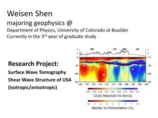
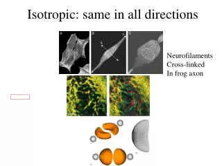
Learn about the differentiation of isotropic and anisotropic minerals through optical methods. Discover the significance of identifying isometric systems and the properties of anisotropic minerals, including double refraction and interference phenomena.

E N D
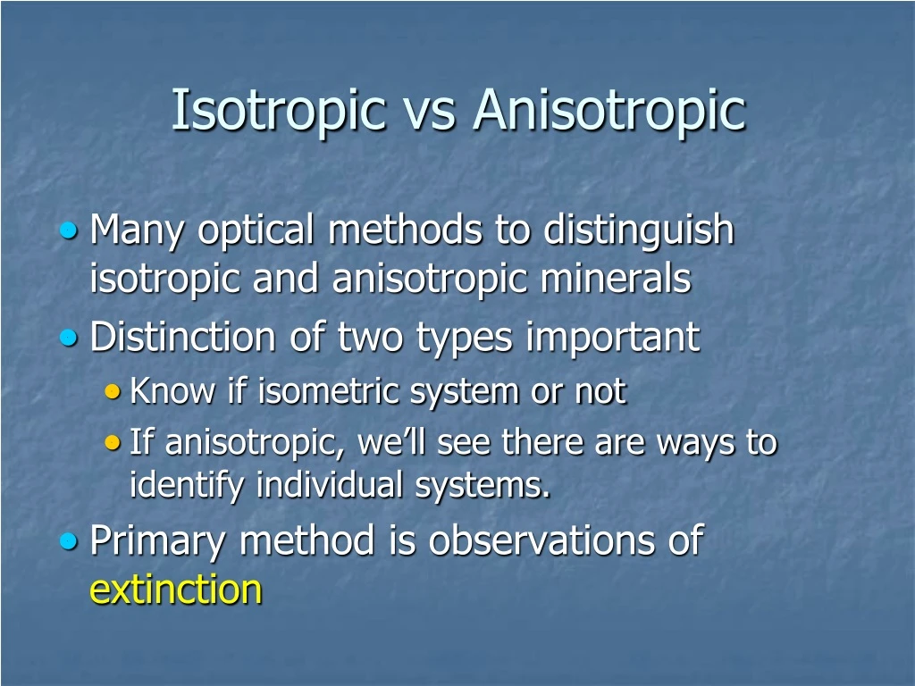
Isotropic vs Anisotropic • Many optical methods to distinguish isotropic and anisotropic minerals • Distinction of two types important • Know if isometric system or not • If anisotropic, we’ll see there are ways to identify individual systems. • Primary method is observations of extinction
Polarizing Microscope Ocular Analyzer, upper polarizer, nicols lens Objective Polarizer, typically oriented N-S
Not Extinct Extinct Quartz crystals in plane polarized light Same quartz crystals with analyzer inserted (cross polarizers aka crossed nicols)
Feldsparpartially extinct, One grain Individual crystals
Extinction in muscovite • Extinction in calcite
Isotropic Minerals • Easily identified • Always extinct with upper polarizer inserted • That is no light passes the upper analyzer • Rotate stage and remains extinct • Vibration direction not changed by material • All light blocked by upper polarizer
Polarizing Microscope Ocular Analyzer, upper polarizer, nicols lens Objective Polarizer, typically oriented N-S
Anisotropic Minerals • Variable values of n within mineral • Has property of double refraction • Light entering material usually split into two rays • Two rays vibrate perpendicular to each other • Caveat: Special section of minerals: light not split and behaves like isotropic mineral – called optic axis • All other orientations: light splits into two rays
Optic axis • Special direction where rays not split into two rays • Wave normal and ray path coincide • Hexagonal and tetragonal have one optic axis • Uniaxial • Orthorhombic, monoclinic, and triclinic have two optic axes • Biaxial
So… light usually split into two rays • For each of the two light rays: • Value of n is determined by vibration direction • In one direction, the value of n is larger than the other • Direction with large N is slow ray • Direction with small n is fast ray • Different values of n mean different angles of refraction – “double refraction”
Interference Phenomena • For most cuts of anisotropic minerals, light not completely blocked by analyzer • Specific color is interference color • Caused by two rays resolving to one ray when they leave the mineral
Interference Colors Not true colors Viewed in crossed nicols (upper polarizer inserted) “Intermediate” interference colors “Low interference colors”
Colored minerals Cross nicols Viewed in plane polarized light Biotite, a pleochroic mineral, natural color Muscovite showing interference colors
YouTube video of pleochroism and interference colors Glaucophane – an amphibole: Na2Mg3Al2Si8O22 (OH) 2
Interference with monochromatic light • Monochromatic = one wavelength • Light split into fast and slow ray • Fast ray travels farther than slow ray in same time • Difference in the distances called retardation, D • Retardation remains same after two rays leave mineral (air is isotropic)
Note: here you need to imagine the two rays follow the same path even though they are refracted Fig. 7-14 D = extra distance fast ray traveled Distance for slow ray Distance for fast ray d = thickness (distance) Typically 30 µm f = v/l; f constantso l changes
Retardation and Birefringence • Derive definition of retardation
Retardation controlled by two things: • Thickness of mineral, d • Difference in speed of fast and slow ray – • (ns – nf) – must be positive number • Units have to be length, typically reported as nm
Birefringence • Birefringence is the difference between ns and nf • d = (ns – nf)
Note: here you need to imagine the two rays follow the same path even though they are refracted Fig. 7-14 D = extra distance fast ray traveled Distance for slow ray Distance for fast ray d = thickness (distance) Typically 30 µm f = v/l; f constantso l changes
Origin of interference colors • Still talking about monochromatic light • If retardation is an integer number of wavelengths: • Components resolve into vibration direction same as original direction • All light is blocked by analyzer
Fig. 7-15a Original polarized direction D = 1,2,3… l Privileged direction of analyzer Resolved vibration direction – Identical to original direction All light blocked = extinct Resolved vibration direction
If retardation is half integer of wavelength • Components resolve into vibration direction 90º to original • Light passes through analyzer
Fig. 7-15b Original polarized direction Resolved vibration directions 90º to original direction Privileged direction of analyzer D = ½, 3/2, 5/2… l All light passes
Fig. 7-4 bloss A more realistic depiction Note – this is still monochromatic light 1½ l 1l 2l 2l From Bloss, 1961
Interference with polychromatic light • Polychromatic light • All wavelengths • Some l = integer value of D • Most l ≠ integer value of D • Interference colors depend on what wavelengths are allowed to pass through analyzer • The wavelengths depend on retardation (D = d*d)
Depending on magnitude of birefringence: • If a narrow band of wavelengths passes through analyzer, see only one color • Sometimes multiple l pass through analyzer, see white
For standard thin section (d=30µm) Interference colors are: Fig. 7-17 Visible l All pass through Quartz: D = 250 nm 1st order white Kyanite: D = 500 nm; 1st order red Violet Red 500/500 = 1 Blue is blocked 750/500 = 1.5 (half integer) 750 l passes through Calcite: D = 2500 nm; 4th order white; cream 2500/416.6 = 6 2500/625= 4 2500/500 = 5 Green Red 416.6, 500, 625 l = full integer, blocked – combined to make white Indigo
Interference Colors Not true colors Viewed in crossed nicols (upper polarizer inserted) “2nd – 3rd order reds and blues” “1st order gray”
Color chart • Shows range of interference colors • depends on retardation • Plot of d (thickness of thin section) versus D (retardation) • Diagonal lines are birefringence, d = ns - nf
Color chart • Divided into orders • Orders are in multiples of 550 nm • Successively higher orders are increasingly washed out • Above 4th order, color becomes creamy white Retardation D (nm)
Color chart • Two Primary uses: • Determine birefringence of mineral • Determine thickness of thin sections • Recall retardation controlled by thickness and birefringence; D = dd • Retardation is simply the observed interference color, D • E.g., the sum of wavelengths that are half integers of retardation.
Determining thickness of thin section • Use quartz (or other easily identifiable, common mineral) • Maximum d is 0.009 • From back of book: ns = 1.553; nf = 1.544 • Actual birefringence depends on orientation of grain Page 232
Maximum birefringence & retardation when c axis is parallel to stage • Birefringence & retardation = 0 when c axis is perpendicular to stage (optic axis) • Intermediate birefringence & retardation for intermediate orientation
Procedure • Find quartz with highest birefringence (correct cut of mineral) • Done by scanning many quartz crystals • Find where the retardation (given by color), intersects lines for birefringence • Calculate it from formula for birefringence: d=D/d • Or read off thickness from chart
Typical slide thickness is 30 µm (0.03 mm) • Quartz will be first order white to yellow • Thin sections may not be perfect • Variable thicknesses • Thin on edges • Thick sections – 70 µm • Used for inclusions • Freeze/thaw of fluid inclusions
Determining birefringence • Maximum d is a useful diagnostic value • Gives the nmaximum and nmiminum of grain • Easily determined in thin section with known thickness • Distribution of birefringence: • Some with zero d • Some with maximum d • Most with intermediate d
Procedure for determining birefringence • Find grain with highest interference colors – most likely to have fastest and slowest n values • Find retardation on the basis of the color (bottom of chart) • Calculate the birefringence using equation: d=D/d • Or find maximum birefringence from chart
Extinction • Many grains in a thin section go dark (extinct) every 90º of rotation • Cause for extinction is orientation of vibration directions • Occurs when principle vibration directions are parallel to vibration directions of upper and lower polarizers • Light retains original polarized direction • Light blocked by analyzer
Extinction Ocular Analyzer, upper polarizer, nicols lens Polarizer, typically oriented N-S
Fig 7-19 Extinct Birefringent
Importance of extinction • Allows determination of principle vibration directions • When extinct, the orientation of the principle vibration directions are N-S and E-W
Extinction in muscovite • Extinction in calcite
Accessory Plates • Primary functions: • Determine optic sign • Determine sign of elongation
Microscopy Ocular Analyzer, upper polarizer, nicols lens Accessory Slot Polarizer, typically oriented N-S
Construction: • Usually gypsum - full wave plate, D = 550 nm • Common mica - ½ wave plate, D = 150 nm • Retardation is known • Orientation of principle vibration directions is known, set at 45º to polarizer and analyzer • Fast ray is length of holder, slow ray is perpendicular to holder
Interference of accessory plate either adds or subtracts from retardation of mineral • With slow ray of mineral parallel slow ray of accessory plate – retardation increases • With slow ray of mineral parallel fast ray of accessory plate – retardation decreases
Net result: • Accessory plate tells you orientation of fast and slow direction in mineral • Important for many optical observations