Download
1 / 7
80 likes | 355 Vues
Hydraulic Hybrid Vehicles. AMESim Model. Controls Flow Diagram. Frame Assembly. Design Process for Spring Semester. Frame Assembly. LabVIEW Simulation. FieldPoint Modules. Functional Requirements. Controls. Team Dumpster Divers - Design Review Snapshot March 8, 2005. Design Matrix.

E N D
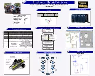
Hydraulic Hybrid Vehicles AMESim Model Controls Flow Diagram Frame Assembly Design Process for Spring Semester Frame Assembly LabVIEW Simulation FieldPoint Modules Functional Requirements Controls Team Dumpster Divers - Design Review Snapshot March 8, 2005 Design Matrix Complete! Detail Design Phase Target Completion Date: Jan. 31st Excel Models Preliminary Design Size Components Design Components Solid Works Models Order Parts Fabrication Target Completion Date: March 11th • Develop Controls • Install Computer (Feb 11th) • Rough Code Development (Feb 18th) • Defined Code Development (Mar. 11th) • Wiring Diagram (Mar. 11th) • Tested Program Ready to Run (by March 21st) • System Components • Take Apart F350 (Feb 7th) • Complete Valve Logic (Feb 11th) • Machine Components (Feb 25st) • Have Reservoir Built (Mar 4th) • Size Hoses (Mar 4th) • Model Hydraulic Schematic in AMESim (Mar 5th) • Assemble Components (Mar 11th) • Tune System (Ready by March 21st) In Progress... • Testing • Target Completion Date: April 8th • Jack Stand Testing (March 30th) • Road Tests (April 8th) • Gather necessary info for analysis • Evaluation & EXPO! • Target Completion Date: April 29th • Data Analysis (April 22nd) • Evaluate Results (April 22nd) • Present at Engineering EXPO (April 29th) Regen Mode Buff System ON DDR – Deliverable DUE DATE: May 7th Accumulator Pressures, Transmission, Engine RPMs. Brake Pressure Which Mode? Accumulator Pressures, Transmission, Velocity, Throttle Pressure Assist Mode Regen Mode Break Pressure Throttle Pressure Inputs Correct? NO NO Inputs Correct? YES YES Open Valve Open Valve Swash Angle? Swash Angle? Accumulator Pressures, Velocity, Throttle Pressure Accumulator Pressures, Velocity, Brake Pressure NO NO Done? Done? YES YES Close Valve Team Members: Michael Shurtliff - EE Seneca Bertovich - CompE Michael Amato - ME Joel Stobie - ME Andi Morey - EE Eric Hake - EE
DFMEA of Current System Team Dumpster Divers - Design Review Snapshot March 8, 20045
Drive Cycle Research Team Dumpster Divers - Design Review Snapshot March 8, 2005 • Hydraulic Assist Cycle (ASSIST) • Best efficiency range for hydrostat as a motor is 500 – 2000rpm (about 10 – 40 mph) • For safety – we want to assist engine at lowest speed possible at higher speed, system must react more slowly due to high fluid flow, which could be dangerous in case of emergency • Regenerative Cycle • (REGEN) • Best efficiency range for hydrostat as a pump is about 2000psi – 4500psi • Goal is to fill accumulator • Approx. 370kJ to fill from 2000psi to 4500psi • Requires an initial regen speed of about 38 mph to obtain 370kJ in accumulator
Electric Charge Pump Team Dumpster Divers - Design Review Snapshot March 8, 2005 • (Point 1 on figure) Diesel engine efficiency very low when at idle • (Point 2) Add 10 N-m of torque from pump through alternator • Efficiency increases due to that engine uses less fuel to do added operation • Conclusion: Run e-pump whenever diesel engine is at idle
New Hydrostat Mounts Team Dumpster Divers - Design Review Snapshot March 8, 2005 After testing, we found the regenerative braking system was very noisy. Most of the system noise is machine borne noise. In an effort to reduce the noise of the system, we had to come up with a dampening scheme. Since the hydrostat acts as both a pump, and a motor, we had to design a mount that would have dampening ability in both directions. The hydrostat’s internal layout also puts forces in the axial direction; we needed to dampen vibrations in that direction as well. The solution was to use an omni-directional vibration dampener. We found the necessary spring rate, and matched it as closely as possible to production vibration dampeners, and came up with a dampener that could isolate the noise up to 77% when the hydrostat was operating at 2500 RPMs.
Scheduled Conferences Team Dumpster Divers - Design Review Snapshot March 8, 2005
Thanks to Our Sponsors Team Dumpster Divers - Design Review Snapshot March 8, 2005