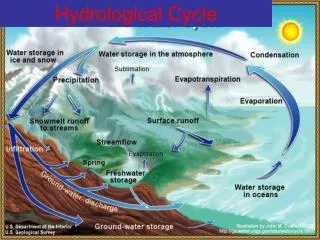
Hydrological Modeling
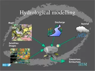
Hydrological Modeling. Overview. Introduction Watershed delineation Automatic delineation Flow length. Introduction. Watershed management. Definition of watershed. “The region draining into a river, river system, or body of water” American Heritage Dictionary

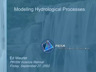
Hydrological Modeling
E N D
Presentation Transcript
Overview • Introduction • Watershed delineation • Automaticdelineation • Flow length
Definition of watershed • “The region draining into a river, river system, or body of water” • American Heritage Dictionary • The upstream area of any given point on the landscape • Physically defined by drainage point and upstream area • Also known as basin, sub-basin, catchment, and contributing area
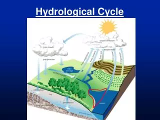
How it works • Water always flows downhill • For any point on a grid representing a landscape,a drop of water can be traced downhill • direction of flow is known for every DEM cell • For any point on a grid representing a landscape,a flow pathway can be traced back uphill • flow accumulation is known for every DEM cell • Uphill back-tracing proceeds to a ridgeline or to the edge of the grid • Termination of uphill back-tracing defines watershed boundary
Watershed delineation • Steps (with ArcToolbox): • Create a depressionless DEM • Calculate flow direction • Calculate flow accumulation • Create watershed Pour points • Delineate watersheds
elevation 1. Creating a depressionless DEM • DEM must eventually drain off edge of grid • Areas of internal drainage will result in unprocessed areas • FILL routine fills in sinks or cuts off peaks creating a new grid with no drainage errors
2. Flow direction • Every cell flows into another cell or off the grid edge • Flow direction is calculated as the direction of steepest downward descent • Flow direction is calculated for each cell, resulting in a new grid theme
flow moves out of a cell in one of 8 directions 2. Flow direction direction of flow is saved as a code number
2. Flow direction north-flowing cells coded as 64
2. Flow direction Flow direction grid
3. Flow accumulation • Each cell has been coded for direction of flow • Cumulative flow is calculated from flow direction • Output grid is created where values are the number of upstream cells • Lower accumulation values are ridge tops • Higher accumulation values are valleys & stream channels
3. Flow accumulation 3 5 1
3. Flow accumulation single class legend shows high flow cells
3. Flow accumulation Fit depends on accuracy of the DEM and stream layers
4. Watershed “Pour points” • Watersheds are defined by outlets (pour points) • Pour points should be placed in high-flow pathways • Basins will be generated from pour point to ridgeline or to upstream sub-basin • Pour points should be numerically coded per sub-basin • Pour points must be converted to a grid layer
Zoom in to place pour point in center of high-flow cell 4. Watershed Pour points • Create as many pour points as necessary
5. Delineating watersheds • Preliminary steps are completed • Filled DEM • Flow direction • Flow accumulation • Pour points created & converted to grid • Run tool to create watersheds
5. Delineating watersheds Watersheds represent area upstream from Pour points and terminate at ridgelines, uphill sub-basin boundary, or edge of the grid
Automatic delineation Pour points automatically selected by “intersection” of highest-flow pathways and grid edge
Flow length Flow distance for every cell to outlet
Flow length Flow distance for every cell to closest stream
Flow length Euclidean distance vs. flow distance
Homework Read:Hydrological Modeling & Watershed Delineation, Map Layouts Study for the exam Presentations: 3/5 Luke, Jennifer, Josh 3/7 Chris, Prati, Carolyn