Download
1 / 36
360 likes | 471 Vues
This presentation outlines the performance reach of the Large Hadron Collider (LHC) beam dump system, focusing on present and future designs to handle higher energy beams. It covers existing dump systems, safety mechanisms, and proposed enhancements for the HE-LHC, aiming for a 16.5 TeV beam dump. Key topics include fast extraction systems, kicker designs, and necessary upgrades to septum magnets. The discussion emphasizes potential challenges and solutions for managing the increased energy density and enhancing system reliability.

E N D
Performance reach of LHC beam dump B.Goddard: input from L.Ducimetière, W.Bartmann, V.Mertens, J.Borburgh, F.Velotti, M.Barnes, C.Bracco, V.Senaj, M.Meddahi, V.Kain, J.Uythoven Joint Snowmass-EuCARD/AccNet-HiLumi LHC workshop ‘Frontier Capabilities for Hadron Colliders’ on 21st and 22nd February 2013
Outline of talk • Introduction • Existing LHC beam dumping system • 16.5 TeV beam dump in present LHC tunnel • 50 TeV beam dump • Summary
Present LHC dump system - concept extract dilute absorb • “Loss-free” fast extraction system • Laminated steel kickers (H deflection) • DC Lambertson septum (V deflection) • Dilution system • Laminated steel ‘sweep’ kickers (H&V) • ~650 m drift length • Beam dump (absorber) block • 7.7 m long, 0.7 m Ø C cylinder, steel and concrete shielding • Protection devices (against asynchronous dump) • Graphite/CC/composite dilutors for septum and LHC machine
Present design - schematic layout 10 x MKB kickers TDE dump block 15 x MSD septa TCDS protection 15 x MKD kickers TCDQ protection Total ‘beamline’ length : 975m from kicker MKD to dump TDE
Present design - tunnel layout Total ‘beamline’ length : 975m from kicker MKD to dump block TDE Dump cavern 40 m
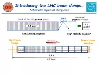
Beam dump block (TDE) • 700 mm graphite core, with graded density of 1.1 g/cm3 and 1.7 g/cm3 • 12 mm wall, stainless-steel welded pressure vessel, at 1.2 bar of N2 • Surrounded by ~1000 tonnes of concrete/steel radiation shielding blocks 0.7 m 3.5 m 3.5 m beam 1.7 g/cm3 1.1 g/cm3 1.7 g/cm3
Assumptions for 16.5 TeV HE-LHC • Reuse existing tunnel and caverns • Same (similar) extraction trajectories in H & V • Similar kicker and septum angles • Maximum ~300 mm dilution sweep radius • Similar quadrupole layout and optics • 2 matching quads in LSS per side of IP (Q4, Q5)
Extraction kickers for 16.5 TeV HE-LHC • New design: reduce vertical opening and increase rise time • Scaling kicker opening to (450/1000): 62 42 mm • Kicker magnetic gap 72 52 mm (vacuum chamber) • 15 magnets, 0.71 T and 31.5 kA: gives 5.1 us rise time • Same installed kicker length • R&D needed on high current switches and high current feedthroughs (19 -> 32 kA), but looks feasible
Dilution kickers and dump for 16.5 TeV • Peak p+ density factor ~2.4 times higher • Shower maximum further into dump block • Total energy to dump ~500 MJ – as for LHC ultimate • Assume sweep length of 100 cm still OK • Effect of smaller beam size may not be an issue at the shower maximum • For beam dump block, would need full FLUKA study to analyse if extra dilution required from MKB kicker system • Likely to require longer block with lower density, or at least different grading of carbon densities • Longitudinal space exists in the UD caverns
Dilution kicker parameters • 7 to 16.5 TeV requires 2.3 times more ∫B.dl • Already near saturation in iron not possible to increase field per magnet • Apertures determined (to first order) by required sweep not possible to reduce magnet gaps (maybe can optimise with two families per plane) • Could keep same maximum Bdlbut increase frequency • 14 to 32 kHz, but increases dI/dt and hence V
Dilution kicker option I • Increase installed length keeping switch voltage at 30 kV • Peak field increases to 1.63 T – just about OK • Needs 22 magnets (presently 10) • Installed length increases to 50.3 m
Dilution kicker option II • Increase frequency, reducing kick angle • Needs 18 magnets total (presently 10) • Total installed length 40 m (presently 22.9) • Will have an impact on the aperture – probably needs few types • As magnets not saturated, gain with higher switch voltage • Need to reach 35 kV
Dilution: Option II – increase frequency • Dilution kicker frequency increase x2 - sweep length 100 cm with spiral ~100 cm sweep length 28 kHz 108 cm sweep length 14 kHz • Potential issues: • Can only realistically build damped sinusoidal field (can’t spiral outwards) so need to cross inner turn with start of the sweep • Temperature profile and mechanical stresses in dump block to evaluate
Dilution system physical installation • 10 magnets presently on extracted beam line in long drift space between IP (extraction septa) and Q4 • 34 magnets – on paper...! Space for generators...? 22 m 50 m
Extraction septa • 15 magnets, 4.5 m long each, to provide total of 2.4 mrad vertically • Lambertson design • 3 types, 0.8, 0.99 and 1.17 T (septum 6, 12, 18 mm) • Need to increase ∫B.dl by factor 2.35
Extraction septa parameters • Use only type B and type C • Thinnest septum anyway not needed behind TCDS • Increase field to maximum possible • Total magnets/beam needed : 28 (14 B + 14 C) • Total installed length is ~136 m (present 73 m) • Assume 32 m extra each side of IP6
28 Extraction septa in layout (R6) 14 20 15 28 Extraction kicker (B2) Extraction septa (B1,B2) Dilution (B1) • Layout maybe just feasible – integration for protection devices and lattice quads?
Dump Protection devices • Long (6 m), low density (C) absorbers intercept undiluted bunches • In front of septum (fixed) and in front of Q4 (mobile) • Fixed 2.4 m steel mask in front of Q4 • Will be difficult for 16.5 TeV
16.5 T dump system outline • 16.5 TeV dump system: does not look impossible in similar layout to present system • 5 ms kicker rise time (new magnet design with smaller gap) feasible • Increase septa ∫B.dl (x1.9 septa length, maybe gain by using more of MSDC type), seems feasible (integration?) • Increase dilution sweep length: higher f0, needs more kickers OR SC dilution quadrupole plus kickers; integration • Upgrade dump block (longer, lower density), seems feasible • Upgrade protection devices; difficult (sacrificial?)
50 TeV beam dump • Key parameters: • 50 TeV energy (x7 wrt LHC ultimate) • 4.5 GJ stored energy (x8.5 wrt LHC ultimate) • 1.5 um transverse emittance • 264 us revolution period • 1.34e11 p+/bunch
50 TeV extraction kickers • Beam rigidity: 167 T.km • Vertical gap of ~40mm (shielded, ~30 mm for beam) • Current of 32 kA (30 kV switches) • Gap field of 0.92 T (peak 1.23 T) • 230 urad deflection with 30 kicker modules • Installed length ~55 m (x2 wrt present LHC system) • Rise time 5.1 us • Can foresee closed orbit bump system at dump septum • Reduce kicker strength requirements • Slow system so easy to interlock • Possibly 5-10 mm deflection at 50 TeV
Extraction kickers • Extraction kicker parameters
50 TeV extraction kicker prefires • Major concern for machine protection • Seen once in LHC in 3.5 years of running – luckily with only one pilot bunch at injection • ~8 sigma deflection per module for VHE-LHC • Very messy with full beam at this amplitude • Two options for mitigation • 1) Retriggering with minimum delay (LHC-like) • Assume 1 us retriggering delay, produces ‘slow’ asynchronous dump sweeep • 2) add “antikicker” to trigger only by pre-trigger • Again with ~1 us turn-on delay • Slowing down kicker rise time is advantage
50 TeV asynchronous dumps • With some good design, pre-trigger of one module can be reduced to (almost) the same load case as an asynchronous dump • Again, seen in LHC, but without beam • ~10x energy density (per swept mm) c.f. LHC • Will rely on passive protection • In front of extraction septum • In front of next lattice quadrupole • In front of experiments • At impacted collimators • Excellent optics control may allow clever design of diluter/sacrificial absorber to protect machine • Also rare event (kicker design and surveillance) • Splitting kickers further could also help (x60??)
50 TeV extraction septa • Around 2 mrad angle at 50 TeV needs 330 Tm! • Scaled-up present LHC system would work…although at least 350 m needed in lattice • Options to explore would be: • Long sequence of normal conducting septa (thin, thick Lambertson, open C-core dipole). Cannot save much in length. • Superconducting septa (not really any issue if they quench with passage of dumped beam)? • Hybrid SC extraction lattice quadrupoles, with passage for extracted beam, ideally providing dipole field for additional deflection? • Make problem easier with “slim” lattice SC quads?
50 TeV dilution system • 4.5 GJ in 264 us • Need to increase dilution sweep length from present LHC ~100 cm to around 700 cm • for same peak energy density per swept linear mm • 12 kHz frequency, sweep length becomes ~750 cm in 264 us, with 2 km drift • Assume same nominal/peak field of 1.13/1.5 T • Switch voltage then becomes 23 kV (from 27!) • Magnets already close to saturation – can’t increase • Installed length increased by x7, to ~160 m • No impact on lattice, as all are in dump line • Sweep diameter ~110 cm (3 turn spiral)
Dilution • Dilution kicker system parameters
Dump block at 50 TeV • Need ~2 km drift from dilution kickers to develop sweep • Inner core ~1.5 m diameter, 10-15 m length? • Thermal stresses need careful evaluation • 4.5 GJ/8 h is about 150 kW average power…. • C? Or sthg more radical: pressurized water? ice?
50 TeV dump system outline • ~60 m, 0.2 mrad extraction kicker (before QD) • 5-10 mm closed orbit bump at septum • 5-6 us abort gap (not much gain to make longer) • Antikicker for pre-trigger mitigation? • Passive/sacrificial septum protection • Extraction septum could be area for studies • SC septum? • Combined lattice SC quadrupole/septum? • “Slim” SC lattice quadrupole? • ~350 m of warm septum??? • Dilution system: 33 kHz, 160 m of kickers • Investigate more elegant options (if we think of any!) • 2 km drift to Ø1.5 m x 10 m CfC dump block?
50 TeV dump system synoptic Dump core + shielding ~50 m Dilution drift ~2000 m Dilution kicker ~160 m Extraction septum + protection ~400 m Extraction kicker ~60 m Kicker-septum drift ~150 m Septum-lattice quad ~200 m ~3000 m
Summary • 16.5 TeV dump system in present LHC tunnel • Extension of present system seems feasible • New extraction kickers, more septa, more diluters • Robustness of protection devices dumps likely to be an issue, but seen in LHC Run 1 to be ‘rare’ events. • 50 TeV dump system for VHE-LHC • It will be a monster (~3 km long from kicker to dump?) • Think about best approach for septum – maybe SC? • However we design them, passive protection devices will likely be sacrificial, … • Dump block thermal loading to look at in detail
Potential R&D directions • High-current switches and feedthroughs • >30 kA needed for VHE-LHC extraction kickers • High voltage, high current, fast turn-on solid-state switches • SC septa • Combined SC quadrupole/septum • “Slim” SC quadrupoles • Sacrificial protection devices • Alternative dilution methods • Beam dump materials/concepts/energy deposition
Temperature rise in dump block Peak energy deposition along dump block length Temperature profile through dump block at Z=250 cm Temperature profile along sweep path at Z=250 cm
Dump protection – difficult with increasing E • Low density to avoid material damage • More total material required to dilute energy density • Very long objects as a result… • ...reduces apertures for extracted beam • Or use sacrificial absorbers – exchange after (hopefully rare) impacts with high intensity Peak GeV/cc in Cu vs beam size at 450 GeV ad 7 TeV • 107 dilution factor, need ~16 lr of C 1.8 g/cc, or ~6 m at 7 TeV • For 107at 16.5 TeV, need ~0.6 - 0.8 g/cc to avoid damage 14-16 m • Some optimisation with graded density to get more lr
(Extra) dilution with SC quad in dump line? 16.5 T 6 m quad @ 100 T/m Dilution quad bmax ~10-20km Present optics bmax ~5km • Present betas: 4-5 km • Add quadrupole to reach about 12 km beta, to get similar sigmas • Need 6 m @ 100 T/m, ~100 mm full aperture • Orbit : 4 mm 45 urad ~30 mm at dump (650 m drift). • Maybe slightly larger absorber block size and dump line : ≈ 0.8 m • Integration likely to be an issue upstream of diluter kickers