Download
1 / 49
490 likes | 589 Vues
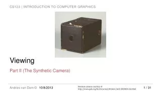
This detailed guide explains 2D and 3D viewing in computer graphics, including projection methods, viewing volumes, normalization, clipping, and perspective division. Learn about the transformation process from modeling to device coordinates and understanding the viewing pipeline. Explore various projection techniques such as orthographic and perspective projections, as well as projection math for transforming 3D points to a 2D plane. The guide is authored by Jim X. Chen and offers valuable insights into the world of graphics viewing.

E N D
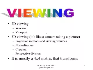
VIEWING • 2D viewing • Window • Viewport • 3D viewing (it’s like a camera taking a picture) • Projection methods and viewing volumes • Normalization • Clipping • Perspective division • It is mostly a 4x4 matrix that transforms @ 2017 by Jim X. Chen: jchen@cs.gmu.edu
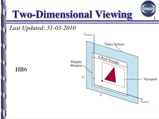
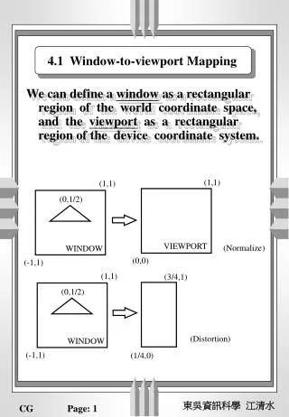
Viewing VIEWING IN 2D • We specify a rectangular area in the modeling coordinates (world coordinates) and a viewport in the device coordinates on the display • window defines what to appear • viewport defines where to display • The mapping of the window (modeling coordinates) to viewport (device coordinates) is a 2D viewing transformation @ 2017 by Jim X. Chen: jchen@cs.gmu.edu
Viewing Y Y Y modeling device normalized X normalized X X modeling device The 2D Viewing Pipeline Specify a window Transform the window Transform the square and the models to the device coordinates in the display viewport. and the models to the in the modeling normalized coordinates. coordinates: area to be displayed Clip against the square T(Center); S(With/2, Height/2); Transform(models); // device models //glViewport() S(2/width, 2/height); T(-center); Transform(models); // normalized models // glOrtho() Clipping(); //generating clipped models // results not available Ex: J2_12_RobotSolar @ 2017 by Jim X. Chen: jchen@cs.gmu.edu .3.
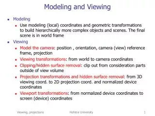
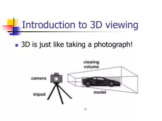
Transformation and Viewing VIEWING IN 3D • In 3D viewing, we specify a viewing volume with a projection method in the world coordinates, and a viewport on the display • Viewing volume specifies what to appear • viewport specifies where to display • The viewing pipeline • … modeling transformation (Lighting calculation in 3D) • The 3D viewing volume is processed for projection methods • Objects are clipped against the 3D viewing volume (z values are preserved for clipping) • The contents are then transformed into the viewport for display • … scan-conversion (z values are preserved for hidden-surface removal) @ 2017 by Jim X. Chen: jchen@cs.gmu.edu .4.
Viewing right top left view point bottom near far The 3D Viewing Pipeline Specify a volume Transform the volume Transform the cube and the models to the device coordinates in the display viewport. and the models to the in the modeling normalized coordinates. coordinates: Clip against the cube volume to be displayed glViewport(x,y,w,h); Trans(models); Draw(models); // device models glFrustum(l,r,b,t,n,f); //glOrtho(l,r,b,t,n,f); Trans(models); // normalized models Clipping(models); // clipped models Ex: J2_12_RobotSolar @ 2017 by Jim X. Chen: jchen@cs.gmu.edu .5.
Viewing right right top left top left view point bottom bottom near near far far PROJECTION METHODS • We deal with only planar geometric projections • If distance from center of projection (viewpoint) to object is finite, projection is perspective; otherwise parallel @ 2017 by Jim X. Chen: jchen@cs.gmu.edu .6.
Viewing Orthographic Parallel Projections : the direction of proj is normal to the proj plane. right top left bottom near far Parallel Projections Oblique Parallel Proj : otherwise. y z OpenGL Viewing x @ 2017 by Jim X. Chen: jchen@cs.gmu.edu .7.
Viewing right top left view point bottom near far Perspective Projections Vanishing point: the perspective projections of any set of parallel lines that are not parallel to the projection plane converge to a vanishingpoint (a point at infinity) If a set of lines is parallel to a coordinate axis, the vanishing point is called the principlevanishing point Perspective projections are categorized by their number of principal vanishing points; current graphics projection only deals with the one point projection OpenGL Viewing z x @ 2017 by Jim X. Chen: jchen@cs.gmu.edu .8.
Viewing @ 2017 by Jim X. Chen: jchen@cs.gmu.edu .9.
void glOrtho(GLdouble left, GLdouble right, GLdouble bottom, GLdouble top, GLdouble near, GLdouble far); 10 OpenGL Orthographic Projection y Viewing Key strokes: Up Arrow: move forward Down Arrow: move backward Right Arrow: move to right Left Arrow: move to left Page up: move upward Page down: move downward z x • The proj is parallel to the z-axis, & the viewpoint faces the negative z-axis. • Positive far and near are used as negative z values (they planes are in front of the viewpoint) @ 2017 by Jim X. Chen: jchen@cs.gmu.edu
11 OpenGL Perspective Projection void glFrustum(GLdouble left, GLdouble right, GLdouble bottom, GLdouble top, GLdouble near, GLdouble far); y z x @ 2017 by Jim X. Chen: jchen@cs.gmu.edu
Viewing right top left bottom near far Orthographic Projection Math (if you really want to put a 3D point into a 2D plane) y Projection parallel to z axis and perpendicular to projection plane z x x/y Portho Portho (x, y, -n) P(x, y, z) z n @ 2017 by Jim X. Chen: jchen@cs.gmu.edu .12.
Viewing right top left view point bottom Near=d far Perspective Projection Math (put a 3D point into a 2D plane) y x/y Pp P(x, y, z) z z n xp /n = -x/z; xp = -x/(z/n); yp /n = -y/z; yp = -y/(z/n); x The projection onto the near clipping plane: Given a point in Perspective Proj, you can consider its (x,y) values are at its projection, and its z value stays: Perspective Proj => Orthographic Proj. (almost true) @ 2017 by Jim X. Chen: jchen@cs.gmu.edu .13.
In matrix form, perspective projection matrix: In homogeneous coordinates Transforming in homogeneous coordinates yields the general homogeneous point: The 3D coordinates can be calculated from the homogeneous coordinates (perspective division, or divide by w): @ 2017 by Jim X. Chen: jchen@cs.gmu.edu
However, we want to keep the z for hidden-surface removal: no linear solution without separating xy and z. F(z) = -(f+n+fn/z) z The 3D coordinates can be calculated from the homogeneous coordinates (perspective division, or divide by w): n<=-z<=f @ 2017 by Jim X. Chen: jchen@cs.gmu.edu
Perspective projection – z forshortening Zp = -(f+n+fn/z) z The 3D coordinates can be calculated from the homogeneous coordinates (perspective division, or divide by w): n<=-z<=f @ 2017 by Jim X. Chen: jchen@cs.gmu.edu
OpenGL Viewing OpenGL Viewing Pipleline Modeling Display Coordinates Device Coordinates Transform Clip against Divide by Normalize the w into the the normalized viewing volume (w may not be 1) for perspective viewport viewing volume projection glOrtho(); glFrustum(); glViewport(); …(3D transformation in homogeneous coordinates) • Specifying a viewing volume - Projection method - Normalization • Clipping • Perspective division • Viewport transformation … (rasterization) @ 2017 by Jim X. Chen: jchen@cs.gmu.edu
Viewing Normalization (Viewing Volume) void glOrtho (GLdouble left, GLdouble right, GLdouble bottom, GLdouble top, GLdouble near, GLdouble far); OpenGL Viewing Which transform an arbitrary viewing volume into a normalized viewing volume: (-1,-1,-1) to (1,1,1) R=S(2/(r-l), 2/(t-b), -2/(f-n)) T(-(r+l)/2, -(t+b)/2, (f+n)/2); @ 2017 by Jim X. Chen: jchen@cs.gmu.edu .18.
x/y glOrtho(l, r, b, t, n, f): (same as translate and scale) Portho P(x, y, z) z n glOrtho(l, r, b, t, n, f) = R=S(2/(r-l), 2/(t-b), -2/(f-n)) T(-(r+l)/2, -(t+b)/2, (f+n)/2); Which transform an arbitrary viewing volume into a normalized viewing volume: (-1,-1,-1) to (1,1,1) @ 2017 by Jim X. Chen: jchen@cs.gmu.edu .19.
Viewing Normalization OpenGL Viewing void glFrustum (GLdouble left, GLdouble right, GLdouble bottom, GLdouble top, GLdouble near, GLdouble far); (left, bottom, -near) and (right, top, -near) specify the (x,y,z) coord of the lower left and upper right corners of the near clipping plane. Which transform an arbitrary viewing volume into a normalized viewing volume. @ 2017 by Jim X. Chen: jchen@cs.gmu.edu .20.
Perspective Projection => Orthographic Projection zp = -(f+n+fn/z) z -n -f The 3D coordinates can be calculated from the homogeneous coordinates (perspective division, or divide by w). Note that z is linear, but 1/z is not, which means when z is big, the difference in 3D coordinates varies very little. @ 2017 by Jim X. Chen: jchen@cs.gmu.edu
Viewing glFrustum(l, r, b, t, n, f): same as glOrtho after perspective transformation x/y Pp P(x, y, z) z n glFrustum(l, r, b, t, n, f) = R=S(2/(r-l), 2/(t-b), -2/(f-n)) T(-(r+l)/2, -(t+b)/2, (f+n)/2)Mper; The 3D coordinates can be calculated from the homogeneous coordinates (perspective division, or divide by w). @ 2017 by Jim X. Chen: jchen@cs.gmu.edu .22.
Viewing glFrustum(l, r, b, t, n, f): same as glOrtho after perspective transformation x/y Pp P(x, y, z) z n @ 2017 by Jim X. Chen: jchen@cs.gmu.edu .23.
ModelView and Projection matrices in OpenGL 4.x • ModelView matrix and projection matrix are self-made, and transferred to vertex shader as uniform • ModelView matrix is considered as transforming a model, or the viewing (projection camera) • Transforming the model or the view is relative to the way of reasoning: depending on how you think @ 2017 by Jim X. Chen: jchen@cs.gmu.edu
Viewing CLIPPING AGAINST THE CUBE • A point (x, y, z) is represented by 6 bits: • Bit 6 =1 if x<left; • Bit 5 =1 if x>right; • Bit 4 =1 if y<bottom; • Bit 3 =1 if y>top; • Bit 2=1 if z<near; • Bit 1=1 if z>far; • A line (2 points) logic OR=0, trivially accepted; logic AND !=0, trivially rejected; • Otherwise intersection is calculated and a line is cut into two; the process continue until all segments are trivially accepted/rejected; • x = x1 + (x2- x1)a; y = y1 + (y2- y1)a; z = z1 + (z2- z1)a; plus the plane equations; • 2D polygon clipping algorithm can be easily extended to 3D as well. @ 2017 by Jim X. Chen: jchen@cs.gmu.edu .25.
Line Clipping against a Plane // how about a line against a plane? GLdouble eqn[4] = {0.0, 1.0, 0.0, 0.0}; glClipPlane (GL_CLIP_PLANE0, eqn); glEnable (GL_CLIP_PLANE0); • A plane equationAx + By + Cz + D = 0 • A 3D line equation x = x0 + t(x1- x0); y = y0 + t(y1- y0); z = z0 + t(z1- z0); The intersection of the line with the plane is at a specific t Example: J2_12_Clipping @ 2017 by Jim X. Chen: jchen@cs.gmu.edu
Viewing glViewport (x, y, width, height); T(Center); S(with/2, height/2, 1); Trans(models); // device models // glDepthRange( GLclampd znear,GLclampd zfar);// 0-1 • The viewport transformation calculates each vertex’s (x, y, z) corresponding to the pixels, and invokes scan-conversion algorithms to draw the model into the viewport. • Projecting into 2D is nothing more than ignoring the z values when scan-converting the model’s pixels into the frame buffer. It is not necessary but we may consider that the projection plane is at z=0. Example: J2_13_ViewPort @ 2017 by Jim X. Chen: jchen@cs.gmu.edu .27.
Viewing & Transformation in Old OpenGL • Mechanism • Programming • GLSL needs completely new way of implementation, but the idea is the same @ 2017 by Jim X. Chen: jchen@cs.gmu.edu
29 Modeling Transformations • Consider the following code sequence: glMatrixMode(GL_MODELVIEW); glLoadIdentity(); glMultMatrixf(N); /* apply transformation N */ glMultMatrixf(M); /* apply transformation M */ glMultMatrixf(L); /* apply transformation L */ glBegin(GL_POINTS); glVertex3f(v);/* draw transformed vertex v */ glEnd(); The vertex transformation is N(M(Lv)); (As we know, the matrices are multiplied together first) • Special matrix multiplications: void glScale{fd}(TYPE x, TYPE y, TYPEz); void glRotate{fd}(TYPE angle,TYPE x,TYPE y,TYPE z); void glTranslate{fd}(TYPEx, TYPE y, TYPEz); @ 2017 by Jim X. Chen: jchen@cs.gmu.edu
30 Viewing Transformation • Analogous to positioning and aiming a camera. • The camera is originally situated at the origin and points down the negative z-axis. • Viewingtransformation are called first modelingtransformation take effect first. @ 2017 by Jim X. Chen: jchen@cs.gmu.edu
31 MODELVIEW MATRIX Another way of looking at the MODELVIEW matrix is that the matrix transforms the viewing method instead of the model. Translating a model along the negative z axis is like moving the viewing volume along the positive z axis. Rotating a model along an axis by a positive angle is like rotating the viewing volume along the axis by a negative angle. Example: J2_13_TravelSolar @ 2017 by Jim X. Chen: jchen@cs.gmu.edu
When we analyze a model’s transformations, logically speaking, the order of transformation steps are bottom-up from the closest transformation above the drawing command to where we specify the viewing volume. When we analyze a model’s transformation by thinking about transforming its viewing, the order of transformation steps are top-down from where we specify the viewing volume to where we specify the drawing command The signs of the transformation are logically negated. Viewing & Modeling (are the same) @ 2017 by Jim X. Chen: jchen@cs.gmu.edu
34 Examples of moving the camera • Going backwards to the moon in generalized solar system: J2_13_TravelSolar • A flight simulator to display the world from the point of view of the pilot: void pilotView{GLdouble planex, GLdouble planey, GLdouble planez, GLdouble roll, GLdouble pitch, GLdouble heading) { glRotated(roll, 0.0, 1.0, 0.0); glRotated(pitch, 1.0, 0.0, 0.0); glRotated(heading, 0.0, 0.0, 1.0); glTranslated(-planex, -planey, -planez); } • Orbiting the camera around an object that’s centered at the origin: y void polarView{GLdouble distance, GLdouble twist, GLdouble elevation, GLdouble azimuth) { x glTranslated(0.0, 0.0, -distance); glRotated(-twist, 0.0, 0.0, 1.0); glRotated(elevation, 1.0, 0.0, 0.0); glRotated(azimuth, 0.0, 0.0, 1.0); } z @ 2017 by Jim X. Chen: jchen@cs.gmu.edu
Viewing Another projection method OpenGL Viewing void gluPerspective (GLdouble fovy, GLdouble aspect, GLdouble znear, GLdouble zfar); fovy -- angle of the field of view in x-z plane (0-180 degree); aspect -- w/h; znear, zfar -- the distances between the viewpoint and the clipping planes along the negative z-axis. The should be always positive. @ 2017 by Jim X. Chen: jchen@cs.gmu.edu .35.
Example: J2_14_Perspective public void myPerspective(double fovy, double aspect, double near, double far) { double left, right, bottom, top; fovy = fovy*Math.PI/180; // convert degree to arc top = near*Math.tan(fovy/2); bottom = -top; right = aspect*top; left = -right; gl.glMatrixMode(GL.GL_PROJECTION); gl.glFrustum(left, right, bottom, top, near, far); } top fovy/2 near @ 2017 by Jim X. Chen: jchen@cs.gmu.edu
void gluLookAt (GLdouble eyex, GLdouble eyey, GLdouble eyez, GLdouble centerx, GLdouble centery, GLdouble centerz, GLdouble upx, GLdouble upy, GLdouble upz); eye -- viewpoint (PRP); center -- reference point (VRP); up -- view up direction (VUP) Viewing from an arbitrary viewpoint OpenGL viewing is always from the center of the coordinates looking down the negative z axis, with the view-up in the y axis direction OpenGL Viewing @ 2017 by Jim X. Chen: jchen@cs.gmu.edu .37.
Example: J2_15_LookAt y public void myLookAt(double eX, double eY, double eZ, double cX, double cY, double cZ, double upX, double upY, double upZ) { //eye and center are points, but up is a vector //1. change center into a vector: goal? // glTranslated(-eX, -eY, -eZ); cX = cX-eX; cY = cY-eY; cZ = cZ-eZ; u c e x z u y y u c c e (eX, eY, eZ); x x e z z @ 2017 by Jim X. Chen: jchen@cs.gmu.edu
y c u //2. The angle of center on xz plane and x axis // i.e. angle to rot so center in the neg. yz plane double a = Math.atan(cZ/cX); if (cX>=0) { a = a+Math.PI/2; } else { a = a-Math.PI/2; } // a is now the angle to rotate c into yz plane e x z y y u u c c (cX, cY, cZ); x a e x e z (cX, cZ); // on XZ plane z @ 2017 by Jim X. Chen: jchen@cs.gmu.edu
y u //3. The angle between the center and y axis // i.e. angle to rot around x axis so center in the negative z axis double b = Math.acos(cY/Math.sqrt(cX*cX+cY*cY+cZ*cZ)); b = b-Math.PI/2; //4. up rotate around y axis (a) radians (up rots accordingly) double upx = upX*Math.cos(a)+upZ*Math.sin(a); double upz = -upX*Math.sin(a)+upZ*Math.cos(a); upX = upx; upZ = upz; //5. up rotate around x axis (b) radians (up rots accordingly) double upy = upY*Math.cos(b)-upZ*Math.sin(b); upz = upY*Math.sin(b)+upZ*Math.cos(b); upY = upy; upZ = upz; c c e x z y c y (, cY, ); u u c b x e x e z z @ 2017 by Jim X. Chen: jchen@cs.gmu.edu
//6. the angle between up on xy plane and y axis double c = Math.atan(upX/upY); if (upY<0) { c = c+Math.PI; } gl.glRotated(Math.toDegrees(c), 0, 0, 1); // up in yz plane gl.glRotated(Math.toDegrees(b), 1, 0, 0); // center in negative z axis gl.glRotated(Math.toDegrees(a), 0, 1, 0); //center in yz plane gl.glTranslated(-eX, -eY, -eZ); //eye at the origin } y u y c c u c x e e x z z @ 2017 by Jim X. Chen: jchen@cs.gmu.edu
Viewing & Transformation in OpenGL Review SpaceView MoonView 42 @ 2017 by Jim X. Chen: jchen@cs.gmu.edu
REVIEW: THE CAMERA ANALOGY Viewing Key strokes: Up Arrow: move forward Down Arrow: move backward Right Arrow: move to right Left Arrow: move to left Page up: move upward Page down: move downward 43 @ 2017 by Jim X. Chen: jchen@cs.gmu.edu
44 • To specify viewing, modeling, and projection transformations, you construct a 4x4 matrix M: v’=Mv. ( Vertices have four coordinates (x,y,z,w), though in most cases w is 1) @ 2017 by Jim X. Chen: jchen@cs.gmu.edu
45 • Modelview matrix: object coordinates to eye coordinates. (specifying camera & obj position) • Projection matrix: eye to clip coordinates. (view volume, normalization, clipping, & projection) • Perspective division: divide coordinate values by w to produce normalized device coordinates. (part of projection) • Viewport matrix: to window coordinates (shrunk or stretched, continuous, float) by applying the viewport transformation. • All the transformations are performed on the z coordinates as well. @ 2017 by Jim X. Chen: jchen@cs.gmu.edu
46 MODELING AND VIEWING TRANSFORMATIONS Suppose the current matrix is C and we call glMultMatrixf(M). After multiplication, the matrix is CM. @ 2017 by Jim X. Chen: jchen@cs.gmu.edu
47 Viewing Transformation • Analogous to positioning and aiming a camera. • By default, the camera is originally situated at the origin and points down the negative z-axis. • Viewingtransformation are called first so that modelingtransformation take effect first. @ 2017 by Jim X. Chen: jchen@cs.gmu.edu
Example: J2_15_LookAt Viewport Transformation The aspect ratio of a viewport should generally equal the aspect ratio of the viewing volume. gluPerspective(myFovy, 1.0, myNear, myFar); glViewport (0, 0, 400, 400); gluPerspective(myFovy, 2.0, myNear, myFar); glViewport (0, 0, 400, 400); To avoid the distortion, this line could be used: glViewport(0, 0, 400, 200); @ 2017 by Jim X. Chen: jchen@cs.gmu.edu
To create two side-by-side viewports, you issue these commands, along with the appropriate modeling, viewing, and projection transformation: glViewport (0, 0, sizex/2, sizey); . . . glViewport (sizex/2, 0, sizex/2, sizey); Manipulating the Matrix Stacks @ 2017 by Jim X. Chen: jchen@cs.gmu.edu