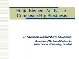
Finite Element Analysis of Composite Hip Prosthesis
370 likes | 687 Vues
Finite Element Analysis of Composite Hip Prosthesis. M. Sivasankar, D.Chakraborty, S.K.Dwivedy Department of Mechanical Engineering Indian Institute of Technology, Guwahati. An overview of hip replacement References on total hip replacement (THR) Objective Material selection

Finite Element Analysis of Composite Hip Prosthesis
E N D
Presentation Transcript
Finite Element Analysis of Composite Hip Prosthesis M. Sivasankar, D.Chakraborty, S.K.Dwivedy Department of Mechanical Engineering Indian Institute of Technology, Guwahati
An overview of hip replacement References on total hip replacement (THR) Objective Material selection Finite element model Comparison of results Scope of the Present Work
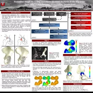
An Overview of Hip Replacement • Anatomy of hip joint • Hip prosthesis • Types of prosthesis fixation • Reasons for hip failure A Typical Hip Prosthesis A Typical Hip Prosthesis
Anatomy of Hip Joint • Largest weight bearing joint • Composed of rounded head of the femur joining the acetabulum of pelvis in a ball and socket arrangement
Reasons for Hip Failure • Long-term aseptic loosening. • Primary hip arthoplasties are subjected to failure due to bone resorption i.e. bone loss. • Failure due to fatigue loading of hip joint. • Relative micro motions resulting from improper implant fitting in the bone cavity.
Reasons for Hip Failure Cont.. • In cementless implants load transfer between a stiff implant and relatively flexible bone results in extremely unnatural stress distribution in bone, i.e. excessive stress concentrations near to the implant ends. • Stress shielding followed by bone resorption in the other areas of bone-implant interface.
Reasons for Hip Failure Cont.. • Hip failure due to bone loss is caused by the production of wear particles associated with the deterioration of the prosthesis • For an average hip patient, the prosthesis have to resist thirty-four million blows
Damaged Femoral Head • Femoral head cartilage • The neck is cut-off as in figure • Marrow cavity is made inside the femur • Hip prosthesis is fitted either by PMMA cement or press fitted
References on Total Hip Replacement Many researchers carried out advanced researches in the field of THR using Finite Element Method and other methods
Literature Review • Researches in this area has been carried out in: • Cemented Joint • Cement less Joint • Finite Element Analysis • Experimental with design models
S.No. Experiment Based FEM based Cemented Joint Cementless Joint 1 G.Bergmann(2001) C.F.Scifert (1999) S.K.Senapathi (2002) P.Kowalczyk (2001) 2 G.Selvaduray(2002) A.Philips (2001) P.Colombi (2002) 3 H.Katoozian (2001) P.Kovalczyk(2001) A.B.Lennon (2003) 4 J.A.Simoes (2000) P.B.Chang (2001) Sheryl Zimmarman (2002) 5 M.Baleani(2000) R.Huiskes (1992) V.Waide (2004) 6 C.Kaddick (1997) C.Li (2002) P.J.Prendergast (1997) 7 N.H.Tai (1995) W.Van Papegem (2001) A.Philips (2001) 8 G.Dillon (1995) S.Srinivasan (2000) C.Li (2002) 9 X.Diao (1997) H.F.El.Sheikh (2003) 10 B.W.Stansfield (2003) S.Gross (2001) 11 M.Pawlikowwski S.H.Teoh (2002) 12 S.L.Evans (1998) Bernard Weisse (2003) 13 R.P.Morris H.Katoozian (2001) 14 M.T.Raimondi (1999) 15 C.M.Styles (1998) 16 I.Hilal (1999) 17 Darryl.D 18 S.Srinivasan (2000) 19 L.J.Lee (1996) 20 W.Vanpaepegem (2002) 21 S.Ramakrishna (2001) 22 K.L.Reifs nider (1991) 23 S.K.Roy Choudhury (2004) 24 A.Rajadurai (2002) 25 R.De.Santis (2004) 26 Vesa Saikko (2002) 27 Debera.E Hurwitz (2003) 28 B.Mavcic (2002) Researches Carried Out
Recent Work Few researchers like A.Phillips[1], P.J.Prendergast [2] ,H.Katoozian [6], C.Li [9] etc., work in the area of cemented prosthesis.
Biomaterials • Stainless Steel Alloys • Cobalt-Chrome alloys (Vitallium) • Titanium alloys • Composites
The isotropic alloys used for stem have much higher stiffness than that of the bone Almost all monoclinic implants have 5 to 20 times more stiffness than the bone A stiff shaft of a total hip prosthesis stress shields the upper part of the thigh bone The shielded bone does not thrive, loses its substance and becomes weak The total hip joint has weak anchorage in a weak skeleton and may fail The remedy is a prosthetic shaft manufactured from metal alloys with stiffness similar to bone Need of Composites
Low stiffness of composite stems can enhance proximal bone ingrowths Tailorability property in strength and stiffness. Excellent biocompatibility A controlled stiffness prosthesis can reduce stress shielding and bone resorption Less weight of the prosthesis Advantages of Composites
Composite Prosthesis • Clinical studies reported early fatigue fracture of a femoral component made from laminated fiber reinforced composites. • The new designs are Constructed of short glass fibers/epoxy resin and CF/PEEK composites.
Composite Model Basic Composite Model With Elements
Conical Stem • Cemented prosthesis model contains three main parts: • Conical Stem with head • Cement layer • Cortical bone Basic Model
Chopped Fiber Core Model With Chopped Fiber Core
Parts Material Young’s Modulus (MPa) Poisson's Ratio Geometrical Parameter (All dimensions are in mm) Head and Stem Ti6Al4V 110x103 0.33 Sphere radius 25 Stem radius 10 Stem outer radius 10 Stem inner radius 7.5 Cement Layer UHMWPE-AL2O3 1x10³ 0.39 Inner radius 10.5 Outer radius 12.2182 Length 100 Cortical Bone AS4/PEEK 3x10³ 0.30 Inner radius 20.5 Outer radius 30 Material Properties Material Properties Used for Analysis of Total Hip Prosthesis
Maximum Shear Stress Region Enlarged View of the Deformed Stem and Cortical Bone Showing the Maximum Shear Stress Region (Path Aa)
Stem Inner Radius (in mm) Stem Length (in mm) Neck Length (in mm) Neck Inclination (in degree) Maximum Shear Stress (in MPa) Maximum Shear Stress (in MPa) Maximum Shear Stress (in MPa) Maximum Shear Stress (in MPa) 45 7.5 45 145 17.314 17.314 13.337 17.314 145.5 47.5 15.522 17.376 47.5 8 20.383 20.655 50 147.5 21.033 17.314 8.5 50 22.964 19.443 52.5 150 25.363 20.919 152.5 17.144 155 20.262 Variation of Shear Stresses Variation of Maximum Shear Stress With System Parameters
Continued... • The variation in the above parameters do not show a particular trend • Hence the design optimization has been carried out to minimize the magnitude of maximum shear stress
Parts State Variables Design Variables Femur Sphere Radius 25 mm Stem Outer Radius 10 mm Stem Inner Radius 7.5 mm Neck Inclination 450 Stem Length 145.5 mm Neck length 50 mm Hip Prosthesis Dimensions of Hip Prosthesis Before Optimization
Design Variables Dimension (mm) Stem outer radius 9.9301 Stem inner radius 8.0405 Stem length 153.22 Neck length 50.975 Femoral Components Design Variables of Femoral Components After Optimisation
Shear Stresses SXY x-ycomponent SYZ y-z component SXZ z-x component Shear Stresses in the Interface of Stem and Cortical Bone
Shear Stresses - Continued… SXY x-ycomponent SYZ y-z component SXZ z-x component Shear Stresses in the Interface of Stem and Cortical Bone
Conclusion • A 3D finite element analysis has been done for analysis of composite hip prosthesis which consists of a conical stem with a cement layer. • Location and magnitude of shear stresses show the region of failure which is in agreement with the earlier published results.
Continued… • As the variation of the parameters do not show a particular trend, design optimization has been carried out to minimize the magnitude of maximum shear stress • The optimum dimensions obtained from the present analysis show considerable reduction in shear stress
References • [1] A. Phillips, 2001, Finite element analysis of the acetabulum after impaction grafting, The University of Edinburgh. • [2] P.J.Prendergast, 1997, Review paper – Finite element models in tissue mechanics and orthopaedic implant design, Clinical Biomechanics, Vol. 12, No. 6, 343-366. • [3] C. F. Scifert, T. D.Brown, J. D.Lipman, 1999, Finite element analysis of a novel design approach to resisting total hip dislocation, Clinical Biomechanics, 14, 697-703. • [4] M.Baleani, M.Viceconti, R. Muccini, M. Ansaloni, 2000, Endurance verification of custom-made hip prostheses, International journal of fatigue 22, 865-871. • [5] P. B. Chang, B. J. Williams, K.S. B.Bhalla, T. W. Belknap, T. J. Santner, W. I. Notz, D. L. Bartel, 2001, Design and analysis of robust total joints replacements: Finite element model experiments with environmental variables, ASME, Journal of Biomechanical .Engineering, 123, 239-246. • [6] H. Katoozian, D. T. Davy, A. Arshi, U. Saadati, 2001, Material Optimization of femoral component of total hip prosthesis using fiber reinforced polymeric composites, Medical Engineering and Physics, 23, 503-509. • [7]S. K. Senapati, S. Pal, 2002, UHMWPE-ALUMINA ceramic composite, an improved prosthesis material for an artificial cemented hip joint, Trends in Biomaterials Artificial. Organs, 16(1), 5-7. • [8] J.Stolk, N. Verdonschot, L. Cristofolini, A. Toni, R. Huiskes, 2002, Finite element and experimental models of cemented hip joint reconstructions can produce similar bone and cement strains in pre-clinical tests, ASME, Journal of Biomechanics 35, 499-510. • [9] C. Li, C. Granger, H. D. Schutte Jr, S. B. Biggers Jr, J. M. Kennedy, R. A. Latour Jr, 2003, Failure analysis of composite femoral components for hip arthroplasty, Journal of Rehabilitation Research and Development, 40(2), 131–146.
A copy of my slides will be available on my website www.biosankar.4t.com My email address is: sivasankar@iitg.ernet.in IITG Biomechanics center: www.iitg.ernet.in Work supported by Department of Mechanical Engineering, contact +91 (361) 2582697 Thank You for Attending…