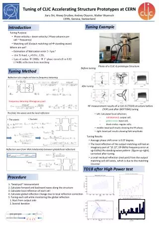
Progress in Accelerating Structure Development for CLIC
Progress in Accelerating Structure Development for CLIC. W. Wuensch CLIC09 12-10-2009. Outline. The near-term program - feasibility demonstration status upcoming events Longer-term program – addressing performance and cost high-power simulation and scaling laws

Progress in Accelerating Structure Development for CLIC
E N D
Presentation Transcript
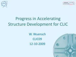
Progress in Accelerating Structure Development for CLIC W. Wuensch CLIC09 12-10-2009
Outline • The near-term program - feasibility demonstration • status • upcoming events • Longer-term program – addressing performance and cost • high-power simulation and scaling laws • cost savings – quadrant structures W. Wuensch
CERN/KEK/SLAC T18 structure tests SLAC1 - done RF parameters KEK - done SLAC2 – under test Average loaded gradient of 100 MV/m W. Wuensch
CERN/KEK/SLAC T18 structure tests SLAC 2 SLAC 1 KEK Lines are E30/BDR=const Chris Adolphsen will cover high-power rf testing in his talk, which is next. Toshi Higo, Valery Dolgashev and Chris will present more details in the rf working group. W. Wuensch
T18 summary • T18 tests clearly shows that there is an rf design which is capable of supporting an accelerating gradient in the range of 100 MV/m. • The rf design was made using newly developed(ing) scaling laws, which contributed to the step from 65 to 100 MV/m. Our scaling laws show that higher efficiency structures at 100 MV/m are possible - the CLIC nominal structure, T24, for example. • The NLC/JLC fabrication technology has now been validated to 100 MV/m. W. Wuensch
Higher-order mode damping Successful demonstration in ASSET in 1999 An Asset Test of the CLIC Accelerating Structure, PAC2000
HOM Damping status • Feasibility of CLIC type heavy damping done. In addition DDS damping and choke mode damping also demonstrated in ASSET. • The wakefield characteristics of the CLIC accelerating structures have been computed with independent means - HFSS, GDFIDL, circuit models, ACE3P – which are also benchmarked against the ASSET experiment. Arno Candel will present the state of the art rf computation in the working group. • This give us confidence that we know the wakefield behavior quite well. • We have a solution for absorbing materials but we must be able to do better. Tatiana Pieloni will present absorber status in the rf working group. W. Wuensch
HOM damping at high power • Do the damping features reduce the gradients which are achieved in undamped structures? We do not have any theoretical model for this effect. On the positive side, the (smaller) openings to the damping manifolds in DDS for NLC/JLC did not affect gradient and (bigger) input/output power couplers work. • Do the damping features introduce technical difficulties to the established and tested fabrication techniques? • Another uncertainty - does the damping material introduce any unexpected high-power performance effects ? • Damping features raise pulsed surface heating. Our baseline fabrication for breakdown gives very soft copper. Can we implement a high gradient preparation and a hard material simultaneously? W. Wuensch
TD18-disk - with damping waveguides SLAC RF parameters KEK Average loaded gradient of 100 MV/m W. Wuensch
CERN/KEK/SLAC TD18 disk structure tests Structures are in final heat treatment – testing at SLAC and KEK should begin around the end of this month. W. Wuensch
CERN fabrication Chris will no doubt report that two recently tested CERN-built X-band disk structures have performed poorly. Sigh. Two major issues: • Since the KEK/SLAC technique – Etch, hydrogen brazing at over 1000°C followed by 10 day 650°C vacuum bakeout – has been reproducibly validated at 100 MV/m, we have decided to adopt it for our next structures. Heavy procedure but we can optimize later. • The X-band results raise important questions about our 30 GHz results. • CERN, KEK and SLAC fabrication covered in talks by Germana Riddone, Toshi Higo and Juwen Wang in the rf working group. W. Wuensch
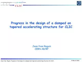
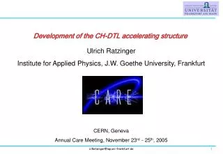
Accelerating structure TD24 (CLIC baseline) after diffusion bonding at 1040 ˚C under Hydrogen Under laminar flow Large grain size! Straightness measurement ±2 mm G. Riddone
Manufacturing at VDL All dimensional checks are conform Damped disk at 12 GHz Shape tolerance ±2.5 mm G. Riddone
Field distribution at the best match • The best match frequency is 3-4 MHz lower than the 120 deg phase advance frequency both in HFSS simulation and measurement • The average phase advance per cell is about 3 deg/cell different at the best match frequency both for HFSS simulation and measurement • There is still residual standing wave even in the case of HFSS simulations where the match is about -40 dB Power for <Eacc> = 100 MV/m
What do the CERN-built X-band results mean for 30 GHz? Is there a reasonable chance that the CERN built 30 GHz structures suffered the same deficiencies as the recent CERN-built X-band structures? Was there is more potential at 30 GHz than we previously thought? Is what we learned from 30 GHz testing still valid? Let’s look carefully before we answer those questions… Point 1: We have not yet inspected the T24 so please give us time to look at it before you draw conclusions. Controversial topic W. Wuensch
Comparing X-band and 30 GHz data Three rf quantities know to be relevant for high-gradients - compilation of data from NLC/JLC and CLIC structures. Black are X-band travelling wave, red X-band standing wave and blue are 30 GHz. Phys. Rev. ABST publication should soon be out. The 30 GHz disk structures, “3.5 mm aperture” are point number 17 – three tests achieved a gradient within 10%. Point 2: The CERN-built 30 GHz disk structures were lower than X-band but not that different. W. Wuensch
Comparing X-band and 30 GHz surfaces Point 3: The 30 GHz disk and CERN-built T18 breakdown and damage patterns are very different: The CERN T18 was dominated by a breakdown hot-spot and damage around contaminant on iris 12. 30 GHz breakdown and damage was systematically concentrated on input coupler. This was identified as an rf design issue which contributed, along with X-band data, to the low group velocity, heavy taper T18 design. But tolerances are too tight to build a 30 GHz T18. So conclusions about rf design remain valid, choice of frequency still driven by tolerances to get to low group velocity. W. Wuensch
High-power rf theory and simulation effort • Over the past couple of decades computational tools have developed to the point that we can now accurately design complex, 3-D and even multi-moded rf structures. • The ability to predict high-power performance has lagged behind: • A lot depends on preparation. But NLC/JLC made enormous progress in improving performance and reproducibility. • The phenomena are extremely complex. • CLIC aims to run very close to the performance limit (for a given breakdown rate) so we had better understand the limit pretty well. W. Wuensch
Understanding breakdown Specifically we would like to understand how the performance depends on geometry and material - gradient for the accelerating structure and power for the PETS and the rf system. Example: Small structure apertures are good for gradient but bad for beam dynamics. Finding optimum requires knowing scaling of gradient. We know that there are different regimes where performance can be limited by electric field, real power flow, complex power flow, pulsed surface heating and dark current capture. A number of simulation studies have been launched to address these questions along with a supporting specialized experimental program. FlyuraDjurabekova will present breakdown physics in two talks and Helga Timko, Jan Kovermann and Jim Norem will present in the working group. W. Wuensch
Sc: high-power design parameter Related to the complex Poynting vector: Travelling wave Standing wave W. Wuensch
Energy of Captured Dark Current vs Location Electrons emitted upstream are accelerated to higher energy (monitored at output end). Cell # 1 20 Simulation • Electron energy as function of emission location. • Eacc=97MV/m. • Higher cell number indicates downstream location
Dark Current Spectrum Comparison “Certain” collimation of beampipe on dark current is considered in simulation data. More detailed analysis Needed. Measured dark current energy spectrum at downstream (need to scale by 1/(pc) Spectrum from Track3P simulation, 97MV/m gradient.
b·E = 10.8 GV/m length and occurence of breakdown clusters ↔ evolution of b Evolution of b during BDR measurements (Cu) spark • breakdown as soon as b > 48 ( ↔ b · 225 MV/m > 10.8 GV/m) • consecutive breakdowns as long as b > bthreshold
The oxide layer of Cu • An oxide layer has been grown on Cu, which was thicker than the natural oxide layer • Higher initial EBRD and conditioning last longer • Has also a different ELOCas the naturally oxidised Cu 125°C, 48h ~ 15nm layer • During conditioning, EBRD=350-500 MV/m in both cases • This lasts only for 15-20 sparks (left case) or 20-40 sparks (right case) 200°C, 72h even thicker layer CLIC workshop 2009
Quadrant quandary Quadrants are a novel topology for making accelerating structures - inspiration to provide a mechanical solution for incorporating damping waveguides in 30 GHz structures. 30 GHz HDS-60 X-band HDX-11 We have tested around ten quadrant structures (although many were not made of copper) and the results have basically been “bad” while disk based structures are working beautifully. But we would like to try quadrants again. Are we nuts? Controversial topic W. Wuensch
Quadrant advantages • COST – The cost working group has estimated that the savings from quadrants would be nearly something very big. • Slotted iris damping is natural with quadrants which leads to much lower pulsed surface heating. This will reduce fatigue and may even reduce breakdown. • No brazing/bonding is necessary for quadrants allowing a much broader choice of materials. But can we avoid heat treatment for breakdown? • PETS are made from octants so quadrant work yields valuable information even if results are equivocal. In reverse the recent success with PETS, Igor Syratchev’s talk later, shows that n-tants can work. Up to a certain level… W. Wuensch
Quadrant performance What performance have we actually achieved. Point 10: HDX- 11. Star was performance for 24 hours before sudden deterioration. Points 19 and 20: HDS-60 run in forward and reverse direction. In summary – the best quadrant tests are only near the worst disk data of disk structures which ran correctly. W. Wuensch
Breakdown cell distribution >2000 Toshi Higo 534 events were analyzed out of 1919 INTLK’s. TD18-quadrant test underway now at KEK. Gradient not high so far but is behavior quadrants, material, preparation or damping waveguides? Come to our working group and help us find out!
Quadrants next • There’s a lot we don’t understand about quadrants but apparently no show-stopper. Rather we have a diverse series of weak points related, but not fundamental, to quadrants. • Yasuo Higashi will support the case for quadrants in rf working group. • Ideas are coalescing for what a new quadrant structure should be, what is the same and what is different to what we have done (slotted but no damping, sealed, hydrogen heat cycle, bake out etc.). We beg of your forbearance – there’s risk but enormous potential payoff. • Further ideas, DDS damping, multimode cavities and externally coupled standing wave cavities are developing – working group presentations of Roger Jones, Sergey Kuzikov and Sami Tantawi. W. Wuensch
Acknowledgements • CAS: High-power/ X-band • components • Tsinghua University: • Acc.structure prototypes • Frascati: PETS manufacturing • Trieste: X-band structure • TERA foundation: Medical • accelerator structures • PSI: X-band structure • EPFL: Damped X-band • structures • Cockcroft: Structure • design • - HIP: Breakdown simulation • VTT: Module design • Finpro: Machining, • Tampere Un. Of Technology: • Management tools • KEK: X-band structure • design, fabrication & testing • IAP, Sumy: • Breakdown studies • NTNU: Breakdown studies, • PETS • CEA / IRFU: TBTS module, • wakefield monitors • SLAC: X-band structure • design, fabrication & • testing, advanced • simulation • Fermilab: BPM studies • NCP: TBTS tanks • Ruhr University of Bochum: • Pulsed surf. heat. fatigue studies • MPI, IPP Grefswald: • Breakdown simulation • - Warner Bruns: RF simulation • RWTH Aachen University: • Breakdown diagnostics • Dubna - JINR: Mechanical • design • BINP – PETS • ILC: Module design, • project tools • ESA: High-power RF • simulation • NorduCLIC: RF design • & fabrication • CIEMAT: TBTS module • IFIC: X-band structures for • medical applications • Petras University: Non- • metallic mat. characterization - DAE: PETS manufacturing • Uppsala: TBTS module, • breakdown experiments