CLIC Accelerating Structure Development
This document outlines the accelerated structure development program for the Compact Linear Collider (CLIC) at CERN, led by W. Wuensch. Key challenges include achieving high gradients of 100 MV/m, minimizing breakdowns, and optimizing beam dynamics with low transverse wakefields and tight phase stability. The presentation emphasizes the importance of collaboration to address these complex issues, covering topics such as RF and linac design, breakdown testing, and advanced simulation techniques. Participation in the lively X-band community is encouraged to enhance CLIC's feasibility.

CLIC Accelerating Structure Development
E N D
Presentation Transcript
CLIC Accelerating Structure Development W. Wuensch XB08 2-12-2008
Introduction • Combined RF and linac design and optimization • High-power limits and breakdown simulation • Fabrication capabilities • High-power testing program • Breakdown and pulsed surface heating experiments • Instrumentation • Other collaborations and X-band projects
Introduction: Our mandate is to develop accelerating structures for CLIC. The key challenges: 100 MV/m, order of 10-7/pulse/m, is the obvious, high-profile, feasibility challenge which we face. The high gradient also creates a life-time issue through pulsed surface heating. Demanding beam dynamics requirements which include low short-range transverse wakefields (consequently micron alignment tolerances), strong long-range wakefield suppression and tight phase stability. These issues are all deeply interrelated as we will see.
The subject of my talk is the structure development program - but what is the point? To introduce important issues and highlight the interrelations amongst them. While doing this I hope to convince you that we have a coherent, thorough and efficient approach. To encourage you to participate in our collaboration! Major effort lies ahead in many areas along with the opportunity for new ideas to make a major impact on the study. • I am personally convinced that the perception of feasibility of CLIC will be significantly enhanced by the existence of a large and vibrant X-band community. • Hence the importance of this workshop. And my sincere thanks to Roger for having taken the initiative in organizing it.
Baseline accelerating structure features HOM damping waveguides 11.994 GHz, 2π/3 so 8.332 mm period Alignment High electric field and power flow region - breakdown Magnetic field concentration – pulsed surface heating Cooling Vacuum pumping Short range wakefields Beam and rf W. Wuensch, CERN
Optimization procedure <Ea>, f, ∆φ, <a>, da, d1, d2 Beam dynamics Bunch population Cell parameters N Q, R/Q, vg, Es/Ea, Hs/Ea Q1, A1, f1 Beam dynamics Structure parameters Bunch separation Ns Ls, Nb η, Pin, Esmax, ∆Tmax rf constraints Cost function minimization YES NO
FoM =Lbx/N · η RF BD Beam dynamics input Lbx/N BD optimum aperture: <a> = 2.6 mm Why X-band ? Crossing gives optimum frequency High-power RF optimum aperture: <a>/λ = 0.1 ÷ 0.12
V. Khan CLIC_ZC structure Coupled Uncoupled Coupled Uncoupled Undamped Undamped Q = 500 Q = 500 Envelope Wake-field Amplitude Wake-field
We can gain enormous benefits with an accurate knowledge of the scaling of high-power limits. One objective we have is a reasonably accurate phenomenological description of the limits to use in high-power structure design. We also are trying to determine the limits from first principles and a theory and simulation effort has begun.
Time constant to reach the copper melting point (cylinders, =30) 100 ns The tips which are of interest for us are extremely tiny, <100 nm (i.e. almost invisible even with an electron microscope) CLIC Breakdown Workshop Sergio Calatroni TS/MME Sergio Calatroni TS/MME 12
Power density at the copper melting point (cylinders, =30) Power density of about 0.5 W/μm2 CLIC Breakdown Workshop Sergio Calatroni TS/MME Sergio Calatroni TS/MME 13
PFN Prf P’rf Field emission and rf power flow Ploss • There are two regimes depending on the level of rf power flow • If the rf power flow dominates, the electric field remains unperturbed by the field emission currents and heating is limited by the rf power flow (We are in this regime) • If power flow associated with field emission current PFN dominates, the electric field is reduced due to “beam loading” thus limiting field emission and heating
Field emission and power flow IFN·E E E·HSW E·HTW
Field emission and rf power coupling What matters for the breakdown is the amount of rf power coupled to the field emission power flow. Assuming that all breakdown sites have the same geometrical parameters the breakdown limit can be expressed in terms of modified Poynting vector Sc. Our new design constraint. Must be less than 6 W/μm2 at 100 ns.
Summary of high-gradient tests Sc = Re{S} + Im{S}/6 A. Grudiev
A Multiscale Model of Arc Discharge Max-Planck Institut für Plasmaphysik, Greifswald, Germany Konstantin Matyash and Ralf Schneider Department of Physics and Helsinki Institute of Physics – University of Helsinki, Finland Helga Timkó, Flyura Djurabekova and Kai Nordlund • Simulations combiningParticle-in-Cell and Molecular Dynamics • Coupling: PIC gives particle fluxes and energy distributions for MD
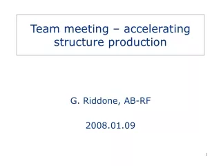
Structure production RF design Mechanical design Tendering CERN-KEK-SLAC collaboration Fabrication Assembly QC
Mechanical design RF INPUT 3D Part Generated 3D Parts S T SmarTeam RF CHECK Assembly Design
Quadrants: machining by milling • machining by 3D milling (carbide or diamond tools) • alignment of the quadrants by pins or balls and gooves (plastic deformation of copper) • assembly by “brazing” or by bolting • damping implemented in the design 160 mm 30 GHz 11.4 GHz Damped quadrants 300 mm
Disks: machining by turning and milling • Disks: machining by diamond turning • Adding damping features Needs milling (no circular symmetry) with smooth transition between milled and turned surfaces. • Alignment of the disks on V-shaped marble before assembly in a stack: use external “cylinder” surface as reference. • Assembly by vacuumbrazing Damped disks VG1 Accelerating structure CLIC G (undamped)
Achieved accuracy (disk) 30 GHz [accuracy in mm] 11.4 GHz [accuracy in mm] Speed bump TD18_disk Specified Achieved Specified Achieved SA: iris shape accuracy OD: outer diameter ID: inner diameter Th: iris thickness Ra: roughness
Dimensional control (TD18) TD18 (VDL) 4 mm
Assembly by brazing Before brazing Holes/grooves for brazing After brazing After brazing , ready for RF check
We have high-power testing program which is made in close collaboration with a number of laboratories, in particular KEK and SLAC . They play a substantial role in not only in structure fabrication and testing but also in analysis/discussion/ideas/ advice/etc. I would like acknowledge their contributions. I will continue here with a focus on CLIC specific testing. Again, we also benefit greatly from other high-gradient and X-band activities some of which are covered by other talks by Valerey, Micha, etc.
The principle elements of our test structure program CLIC prototype: Nominal CLIC accelerating structure, CLIC_G with damping and made from brazed copper disks. This test is scheduled for spring 2009. Near CLIC prototype: Other structures to approach CLIC_G one step at a time to isolate the influence of individual features. One example is a CLIC_G without damping, to determine the effect of the damping features. Quadrant structures: More adaptable to alternative materials for both breakdown and especially pulsed surface heating and shares fabrication technology with the PETS. BUT quadrant accelerating structures have worked poorly. We still don’t understand why.
The principle elements of our test structure program Ten-cell structures: Smaller, cheaper, faster structures using SLAC re-useable couplers for investigations to test new ideas and support theory and simulation. Examples include alternative damping features and iris scaling. Dedicated experiments: To support breakdown theory and simulation using various structures. Examples include staircase pulse-shape, bi-periodic pulse train, long-pulse induced fatigue, reversed structures. Collaboration structures: Not made to CLIC targets but can provide important experience and information. H75 for PSI and Trieste are an example.
T18 – Successful fabrication and test of the first CLIC X-band test structure designed for 100 MV/m, low breakdown rate operation. Lines of breakdown rate vs gradient tradeoff CLIC breakdown rate specification 18 undamped cells, 29 cm long, 2.6 to 1% tapered group velocity and manufactured by diamond turning and diffusion bonding. The result – After steady improvement, operation below the 4x10⁻⁷ CLIC breakdown rate specification with above 105 MV/m unloaded gradient. Excellent collaboration - designed by CERN, manufactured by KEK and bonded and tested by SLAC.
From T18 to prototype Supporting tests: Quadrant fabrication CD10 Choke mode CD10 TD18 Add damping Move to design iris range Move to design iris range and add damping CLIC_G with damping, full prototype T18 tested to 105 MV/m, 230 ns, 2x10⁻⁷/(mxpulse) Add damping Move to design iris range Supporting tests: C10 series T23 CLIC_G undamped mid to late 2009 Today early 2009
Achieved results to prototype CLIC structure CLIC prototype T18 test structure
Staircase pulse shape • No influence on BDR for gradients below 80% • Strong influence on the BDR for gradients above 90% • Very good agreement with SLAC data 119 MV/m 111 MV/m 100 % 93 % in gradient *:Max gradient in the structure main pulse sub pulse after pulse Chris, Faya SLED output pulse
MASTER SCHEDULE (1/2) 04.12.2008
MASTER SCHEDULE (2/2) 04.12.2008
Experimental set-up : ‘‘ the spark system ’’ vacuum chamber (UHV 10-10 mbar) HV switch HV switch m-displacement gap 10 - 50 mm (±1 mm) 20 mm typically anode (rounded tip, Ø 2.3 mm) power supply (up to 15 kV) V spark C (28 nF) cathode (plane) • Two similar systems are running in parallel now • Types of measurements : Field Emission ( b) Conditioning ( breakdown field Eb) Breakdown Rate ( BDR vs E)
g = power in the fit BDR ~ Eg Breakdown Rate : DC & RF (30 GHz) Same trend in DC and in RF, but difficult to compare ‘slopes’
no visible increase in outgassing just before a breakdown cluster H2 outgassing in Breakdown Rate mode (Cu)
Are small tips pulled by the field? (we need more data) Evolution of b during BDR measurements spark • quiet period low b • b seems to increase (a few %) during a quiet period if E is sufficiently high
effect of the oxide breakdown field mutliplied by 2 at least conditioning observed layer thickness = ‘‘15 – 20 sparks’’ DC spark test on oxidized copper • We still need to • characterize the layer • control the layer • understand what’s going on Cu … but the effect is real !
HIP2 (KEK) 33 Single Crystal Cu (KEK) ?? 19 Cu101 (SLAC) 10 KEK3 (KEK) CuCr102 (SLAC) CuZr3-2 (CERN) 77 83 Pulse Heating Samples RF Tested May 2008 – September 2008 E-Deposited Cu (KEK) 62 Lisa Laurent, SLAC Hardness Test Value
CEA Saclay collaboration in CLIC Module • Objectives: • Accelerating structure performances with beam: 11.9942 GHz, 100 MV/m, 150ns bunch train … • Precise structure alignment for bunch train emittance preservation • → determination of the accelerating structure position with respect to the beam by the EM fields excited by the beam = Wakefield Monitors (WFM) Development plan: 1) Detailed design of WFM and procurement of a prototype for integration in a CERN accelerating structure and test on the Two Beam Test Stand with CALIFES probe beam (2009) Kick-off meeting at CERN: 8 Dec. 2008 First beam in RF gun: 27 Nov. 2008 ! 2) Design and procurement of complete accelerating structures including WFM (2010) In the framework of the Clic French Contribution (CFC) 1/3
Accelerating Structure • RF Design • CLIC_G structure: R/Q=, Q=, 24 cells, 120° advance per cell, 230mm active length, tapered iris for constant gradient, Heavy damping by orthogonal waveguides + RF absorbers HFSS model of one cell GdFidl simulation of complete structure (CERN result) • Fabrication • Technology: precise machining of copper disks, high temp. brazing, sealed structure • → Mecachrome for machining ? → Bodycotte for brazing ? 2/3
Wakefield Monitors • RF Design • One transverse position detector per structure, located at the middle cell • Four couplers in orthogonal position integrated in the damped waveguides Or loop, antenna… • Electronics • 180° hybrid coupler in waveguide or striplines • Fast digital scope (feasibility demonstration) • D port for offset measurement (dipole signals have opposite phase at the two opposite waveguides) • S port for beam intensity measurement (monopole signals have the same phase) • Performances • Good linearity, resolution ~ 1 µm, precision ~ 10 µm • Should not low cost ( quantity of 140000 WFM for CLIC!) 3/3