Understanding Data Registers and Counters in Digital Systems
290 likes | 412 Vues
Chapter 6 overview discusses the role of multiple flip-flops in forming data registers. It explains shift registers for transferring data serially or in parallel, highlighting their application in arithmetic units and digital hardware. The chapter explores various types of registers, including those with parallel load and asynchronous clear functions. Additionally, it covers serial versus parallel data transfer, the properties of ripple and synchronous counters, and practical applications in computers and peripherals. Gain insights into building efficient digital circuits and designing counter mechanisms.

Understanding Data Registers and Counters in Digital Systems
E N D
Presentation Transcript
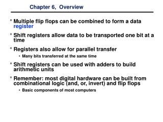
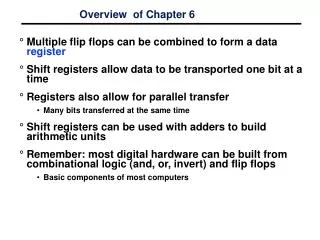
Overview of Chapter 6 • Multiple flip flops can be combined to form a data register • Shift registers allow data to be transported one bit at a time • Registers also allow for parallel transfer • Many bits transferred at the same time • Shift registers can be used with adders to build arithmetic units • Remember: most digital hardware can be built from combinational logic (and, or, invert) and flip flops • Basic components of most computers
Register with Parallel Load • Register: Group of Flip-Flops • Ex: D Flip-Flops • Holds a Word (Nibble) of Data • Loads in Parallel on ClockTransition • Asynchronous Clear (Reset)
Register with Load Control • Load Control = 1 • New data loadedon next positiveclock edge • Load Control = 0 • Old data reloadedon next positiveclock edge
Shift Registers • Cascade chain of Flip-Flops • Bits travel on Clock edges • Serial in – Serial out, can also have parallel load / read
Parallel Data Transfer • All data transfers on rising clock edge • Data clocked into register Y
Parallel versus Serial • Serial communications is defined as • Provides a binary number as a sequence of binary digits, one after another, through one data line. • Parallel communications • Provides a binary number through multiple data lines at the same time.
Shift register application • Parallel-to-serial conversion for serial transmission parallel outputs parallel inputs serial transmission
Serial Transfer • Data transfer one bit at a time • Data loopback for register A Time T0 T1 T2 T3 T4 Reg A 1011 1101 1110 0111 1011 Reg B 0011 1001 1100 0110 1011
Serial Transfer of Data • Transfer from register X to register Y (negative clock edges for this example)
OUT OUT1 OUT2 OUT3 OUT4 D Q D Q D Q D Q IN CLK Clk IN OUT1 OUT2 OUT3 OUT4 OUT Before 1 1 0 0 0 0 0 2 0 1 0 0 0 0 3 0 0 1 0 0 0 4 1 0 0 1 0 0 5 0 1 0 0 1 1 Pattern recognizer • Combinational function of input samples • in this case, recognizing the pattern 1001 on the single input signal
Serial Addition (D Flip-Flop) • Slower than parallel • Low cost • Share fasthardware onslow data • Good for multiplexed data
Serial Addition (D Flip-Flop) • Only one full adder • Reused for each bit • Start with low-order bit addition • Note that carry (Q) is saved • Add multiple values. • New values placed in shift register B
Serial Addition (D Flip-Flop) • Shift control used to stop addition • Generally not a good idea to gate the clock • Shift register can be arbitrary length • FA can be built from combin. logic
Universal Shift Register • Clear • Clock • Shift • Right • Left • Load • Read • Control
Summary of Registers • Shift registers can be combined together to allow for data transfer • Serial transfer used in modems and computer peripherals (e.g. mouse) • D flip flops allow for a simple design • Data clocked in during clock transition (rising or falling edge) • Serial addition takes less chip area but is slow • Universal shift register allows for many operations • The register is programmable. • It allows for different operations at different times • Next time: counters (circuits that count!)
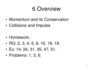
Counters Overview • Counters are important components in computers • The increment or decrement by one in response to input • Two main types of counters • Ripple (asynchronous) counters • Synchronous counters • Ripple counters • Flip flop output serves as a source for triggering other flip flops • Synchronous counters • All flip flops triggered by a clock signal • Synchronous counters are more widely used in industry.
Counters • Counter: A register that goes through a prescribed series of states • Binary counter • Counter that follows a binary sequence • N bit binary counter counts in binary from n to 2n-1 • Ripple counters triggered by initial Count signal • Applications: • Watches • Clocks • Alarms • Web browser refresh
Binary Ripple Counter • Reset signal sets all outputs to 0 • Count signal toggles output of low-order flip flop • Low-order flip flop provides trigger for adjacent flip flop • Not all flops change value simultaneously • Lower-order flops change first • Focus on D flip flop implementation
Another Asynchronous Ripple Counter • Similar to T flop example on previous slide
A3 A2 A1 A0 0 0 0 0 0 0 0 1 0 0 1 0 0 0 1 1 0 1 0 0 0 1 0 1 1 0 0 0 1 0 0 1 Asynchronous Counters • Each FF output drives the CLK input of the next FF. • FFs do not change states in exact synchronism with the applied clock pulses. • There is delay between the responses of successive FFs. • Ripple counter due to the way the FFs respond one after another in a kind of rippling effect.
Synchronous counters • Synchronous(parallel) counters • All of the FFs are triggered simultaneously by the clock input pulses. • All FFs change at same time • Remember • If J=K=0, flop maintains value • If J=K=1, flop toggles • Mostcounters are synchronous in computer systems. • Can also be made from D flops • Value increments on positive edge
Synchronous counters • Synchronous counters • Same counter as previous slide except Count enable replaced by J=K=1 • Note that clock signal is a square wave • Clock fans out to all clock inputs
Circuit operation • Count value increments on each negative edge • Note that low-order bit (A) toggles on each clock cycle
Synchronous UP/Down counters • Up/Down Counter can either count up or down on each clock cycle • Up counter counts from 0000 to 1111 and then changes back to 0000 • Down counter counts from 1111 to 0000 and then back to 1111 • Counter counts up or down each clock cycle • Output changes occur on clock rising edge
Counters with Parallel Load • Counters with parallel load can have a preset value • Load signal indicates that data (I3…I0) should be loaded into the counter • Clear resets counter to all zeros • Carry output could be used for higher-order bits
Clear Clk Load Count Function 0 X X X Clear to 0 1 ↑ 1 X Load inputs 1 ↑ 0 1 Count 1 ↑ 0 0 No Change Function Table Counters with Parallel Load • If Clear is asserted (0), the counter is cleared • If Load is asserted data inputs are loaded • If Count asserted counter value is incremented
Binary Counter with Parallel Load and Preset • Presettable parallel counter with asynchronous preset. If PL’ = 0, load P into flops
Binary Counter with Parallel Load and Preset • Commercial version of binary counter
Summary • Binary counters can be ripple or synchronous • Ripple counters use flip flop outputs as flop triggers • Some delay before all flops settle on a final value • Do no require a clock signal • Synchronous counters are controlled by a clock • All flip flops change at the same time • Up/Down counters can either increment or decrement a stored binary value • Control signal determines if counter counts up or down • Counters with parallel load can be set to a known value before counting begins.