Download
1 / 27
270 likes | 409 Vues
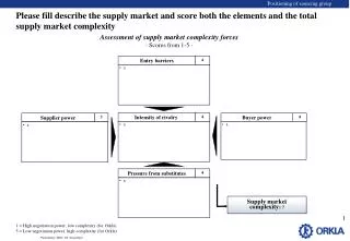
Low-Power High-Accuracy Timing Systems for Efficient Duty Cycling. Thomas Schmid, Jonathan Friedman, Zainul Charbiwala , Young H Cho, Mani B Srivastava {schmid, jf, zainul, young, mbs}@ee.ucla.edu. Duty Cycling with Accurate Clocks. Most WSN applications have a need for synchrony

E N D
Low-Power High-Accuracy Timing Systems for Efficient Duty Cycling Thomas Schmid, Jonathan Friedman, Zainul Charbiwala, Young H Cho, Mani B Srivastava {schmid, jf, zainul, young, mbs}@ee.ucla.edu
Duty Cycling with Accurate Clocks • Most WSN applications have a need for synchrony • MAC protocols that utilize Scheduling and LPL • Synchronous sensing (for beam forming applications) • Minimizing guard bands to reduce wasted active-time and increase channel capacity Guard band to overcome clock drift Compute Transmit Sense Sleep
Duty Cycling with Accurate Clocks • Duty cycling is a key mechanism for conserving energy • A timer remains active while the node is asleep • As duty cycle decreases, sleep power starts to dominate average power consumption Guard band to overcome clock drift Compute Transmit Sense Sleep
Observations Accurate clocks can save energy by reducing guard times For equal guard times, a node with a more accurate clock can sleep longer But, we must ensure that this accuracy does not come at increased cost
Balancing Stability, Granularity and Power Granularity + Stability = Power
Outline • Introduction • Differential Frequency Error • XCXT Prototype Implementation • Evaluation and Power Numbers • The Smart Timer Unit • Conclusion
Some Nomenclature • Temperature dependent Frequency: • Nominal Frequency: • Frequency Error: • Normalized Error: • Differential Frequency Error:
Frequency - Temperature Dependence of AT-cut • AT-cut Quartz crystals inside most XOs today • Characteristic cubic temperature curve with slope dependent on slight variations in cut angle
Differential Frequency Error Normalized Frequency Error vs. Temperature
AT-cut Quartz Crystals Differential Frequency Error vs. Temperature
AT-cut Quartz Crystals Normalized Frequency Error vs. Differential Frequency Error Compensate Lookup Measure
Exploiting Differential Frequency Error • If is a bijection, we know there exists a unique mapping from differential frequency error to the temperature • Then, we construct the curve using a stable clock reference (factory calibration) • At run time, we measure and then estimate using the calibration curve • Compensating by this amount, we can achieve the same stability as the factory reference
Why not use a Temperature Sensor? Cons: • Temperature sensor itself requires calibration • Hysteresis due to unequal heating of sensor and crystal • Temperature sensor needs an ADC Pros: • DFE measures the phenomena of interest directly – frequency error • DFE can be all digital and lower power
Compensation Results (Simulation) • Using 1’ and 8’ AT-cut Quartz crystals • Compensation ‘gain’ of about 40x (16dB)
Maximum Gain vs Cut Angle Difference 16 14 12 10 8 Gain [dB] 6 4 2 0 0 -3 -2 -1 0 1 2 3 Cut Angle Difference [minutes] Change in Angle
XCXT Prototype Implementation • Telos mote with MSP430 µC • MSP430 has 2 crystal inputs • Added a small extension board that holds the two crystals • Replaced standard 32kHz clock with a 8MHz crystal • Software using SOS operating system for calibration and compensation • Temperature chamber to cool and heat the device: -10℃ to 60℃
8MHz Crystal Measurements • Kyocera HC49SFWB and FOX HC49SDLF • 8.000 MHz fundamental frequency with 50ppm stability
XCXT Compensation We achieve a mean stability of 0.47ppm with a sample standard deviation of 0.31ppm
8MHz XCXT Power Measurements Compensation Calculations Timer Overflows • Average Current: 474 μA at 3.001V • Average Power: 1.4 mW compared to 6 mW of a DS4026 TCXO
How does Granularity affect Timer Power? • For 8MHz, MSP430 is in LPM1 - timers are active, but CPU is shut down • For 32kHz measurement, MSP430 is in LPM2 - secondary clocks are off, CPU off Need this power With this granularity
Exploiting Temperature Dynamics • Temperature changes slowly (max. 1°C per minute) even in outdoor environments • Clock correction/compensation needed only once a minute • Can adapt to actual rate of change through DFE based temperature sensing • But, increasing interval between compensations would save some power but not much
Smart Timer Unit • Use 32KHz clock as primary during sleep, 8MHz XCXT as duty cycled secondary • Use 8MHz XCXT in the last 32KHz pulse to increase granularity • Exploit higher stability of the XCXT to compensate the 32KHz once every minute 8M 8M XCXT STU 32K Periodic XCXT correction STU always on Active Active Sleep
Preliminary Simulation Results Below 300µW
Conclusion • Compensating a pair of AT-cut crystals using Differential Frequency Error can provide sub-ppm accuracy • A prototype implementation verifies lower power ability of XCXT • Even lower power can be achieved using a coarse granularity timer corrected by a duty cycled XCXT
Related Work • Use two different cut crystals (AT-cut & Y-cut) [Onoe 1975] • Use of one SC-cut crystal and two harmonics [Schodowski 1983]This became the MCXO (~70mW, instead of ~1.5W for an OCXO with the same precision) • Use two AT-cut crystals for temperature measurement, [Satou 1991]